 EN_US
EN_US  İspanyolca
  Русский
  العربية
  Portekizli Brezilya
  Fransızca
  Bahasa Indonesia
  Türkçe
  Tiếng Việt
  Bahasa Melayu
  Українська

 Teknik Bilgi
Teknik Bilgi
Köprü Kirişi Taşıyıcı Yük Hesaplaması Açıklaması: Köprü Kirişlerinin Güvenli Taşınmasını Nasıl Sağlarsınız?
Genel Bakış
In large bridge construction sites, the ışın taşıyıcı is the project’s artery. Even with the most expensive equipment, early calculation errors can cause risks. The whole artery may face the risk of collapse at any time. This means high repair costs for equipment. It is also a major hidden danger to progress and worker safety. Load calculation is never simple number addition and subtraction. It involves static load stability and dynamic braking impact effects. It is a complex mechanical game under extreme working conditions. In practice, many teams ignore key variables like road flatness fluctuations. They also ignore the distribution of steering acceleration. This leads to severe axle load overruns. It shortens equipment life and directly threatens construction safety.
This article skips boring theoretical formula stacking. We will explain the beam transporter load calculation logic from a practical view. We will guide you through the complete process. This covers from beam static load analysis to dynamic safety checking. We will deeply analyze those hidden risk points ignored by the industry. Are you worrying about complex span beam transport plans? Or do you want to avoid safety accidents through scientific calculations? This article will be your most practical guide to avoid pitfalls.
Why is beam transporter load calculation so important?
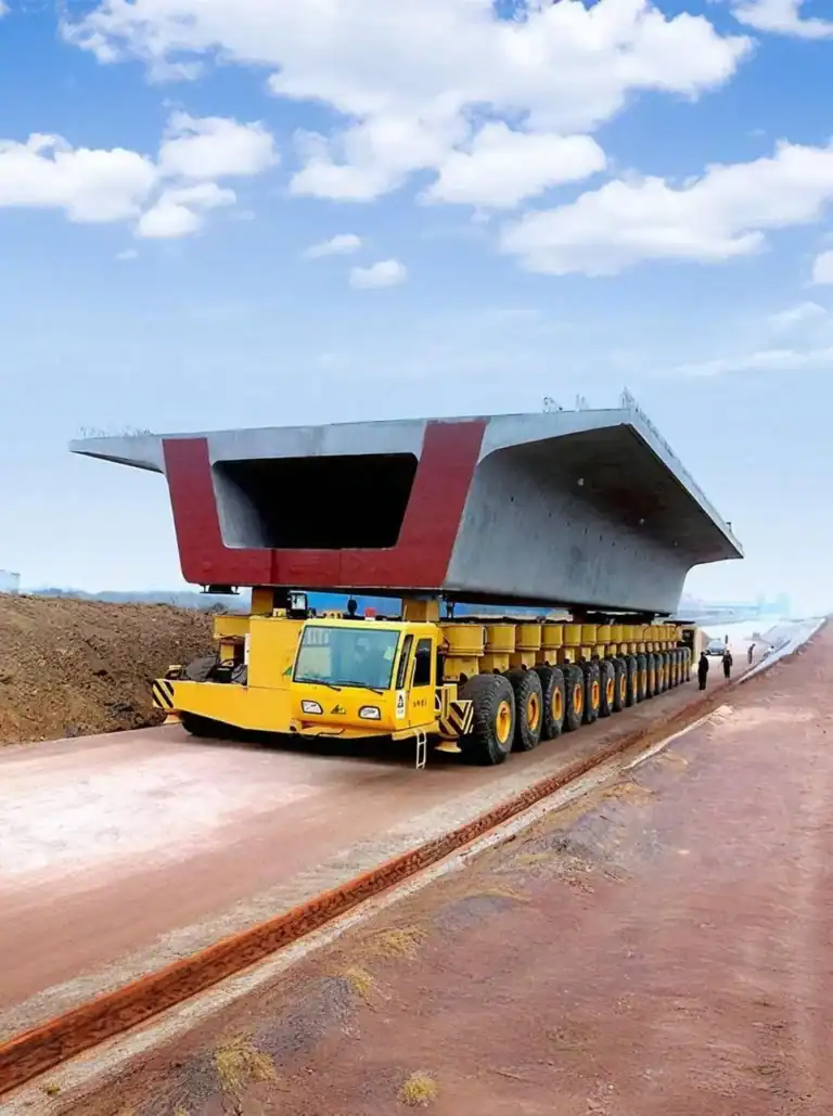
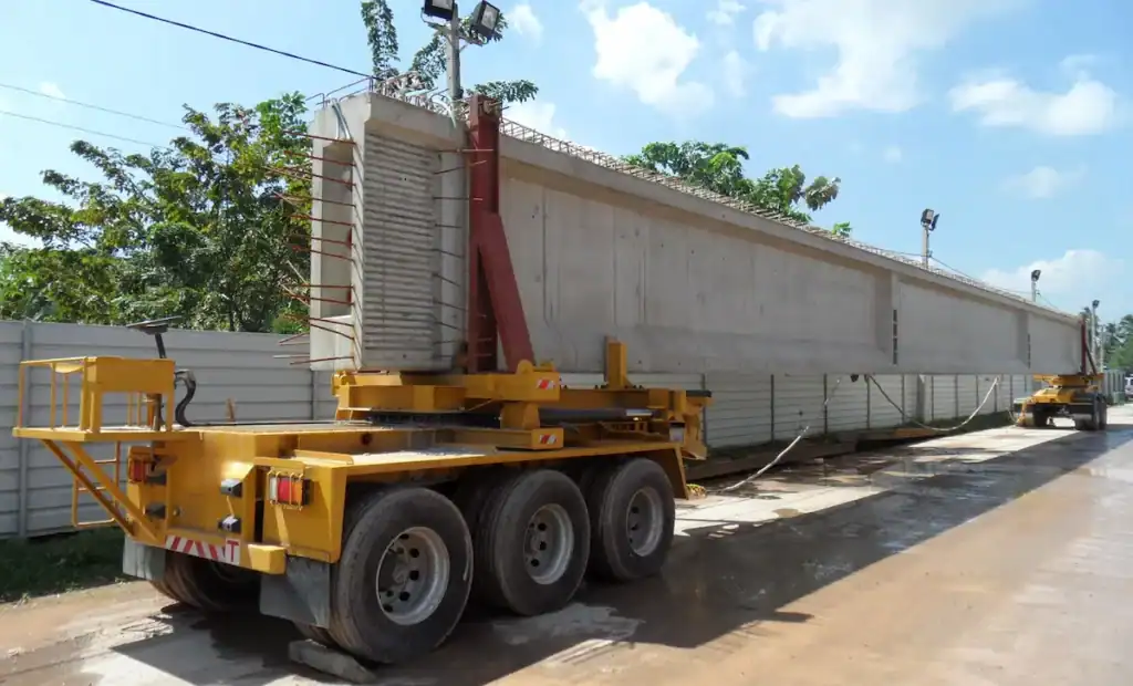
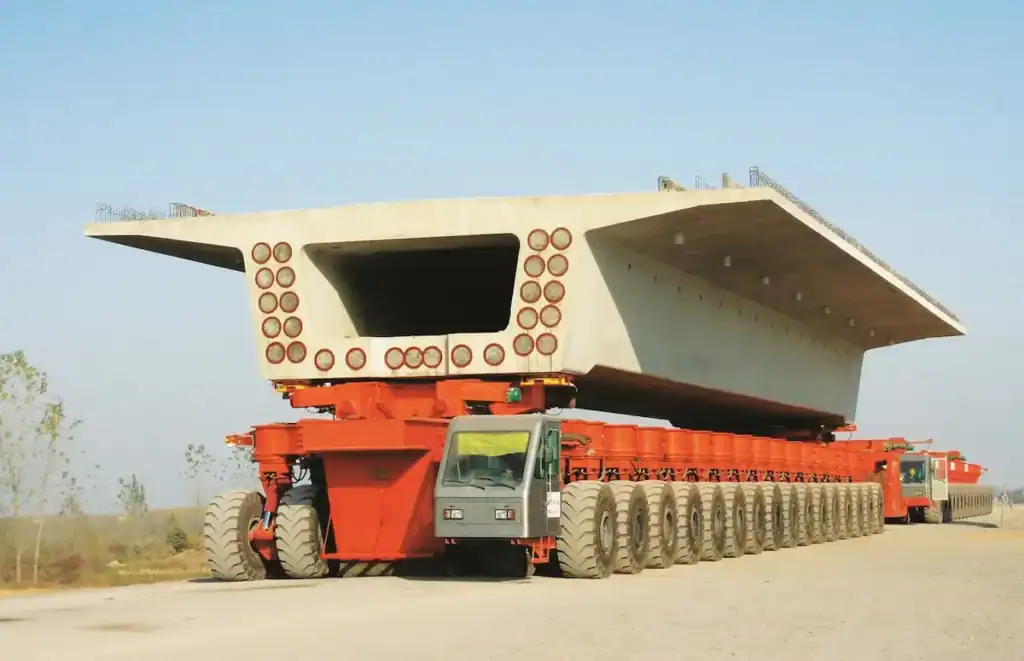
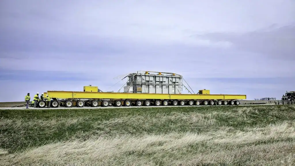
In the bridge engineering field, there’s a common joke: “Once the beam transporter starts moving, the project manager gets nervous.” This is far from an exaggeration. Beam transporter load calculation relies on precise physical and mechanical formulas to determine how precast beams weighing tens or even thousands of tons affect the vehicle under different operating conditions. These calculations consider the beam at rest, during climbing, steering, braking, and while traveling over uneven roads. The analysis also determines the actual forces acting on every tire, axle, and girder. Rather than simply matching the beam weight to the vehicle’s rated capacity, it involves a dynamic mechanical simulation with millimeter-level displacement accuracy and Newton-level force calculations.
The Relationship Between Load Calculation and Transport Safety
Think of beam transport as a battle. Load calculation is the only sandbox simulation. Below is a stark contrast between precise calculation and blind estimation:
| Risk Dimension | State After Precise Calculation | Consequences of Estimation or Wrong Calculation |
| Frame structure | Bending moment and shear are within safety limits. The vehicle body has zero fatigue damage. | Local stress severely exceeds standards. The main girder bends irreversibly or breaks directly. |
| Hydraulic suspension | Suspension grouping is scientific with balanced pressure. Ramps automatically achieve dynamic compensation. | Local cylinders instantly lock and burst. The whole vehicle completely loses balance in seconds. |
| Tire grounding | Axle load distribution is uniform. Tire loads meet standards to avoid local overheating. | Unbalanced loads double single-side tire loads. Sudden chain tire blowouts occur during transport. |
| Road and bridge safety | Ground pressure is completely controllable. It does not destroy temporary roads and bridges. | It crushes temporary bridges and sinks subgrades. This causes the vehicle to roll over or get stuck. |
Briefly Explain Why Wrong Calculations Easily Cause Accidents
Many novice engineers often make a common mistake. They directly use static weight as the design basis.
Real pain points: When the beam is static, the center of gravity is geometric. But once the vehicle moves, the situation changes completely. Even a 2% slight cross slope changes things. A slight emergency braking will shift the gravity line instantly. Box beams or T-beams can be several meters high. This shift creates a huge overturning moment at the bottom. Early calculations must leave enough dynamic safety margins. Otherwise, the instant resultant force on a single suspension surges parabolically. It may exceed the compensation limit of the hydraulic system. Then, the vehicle will instantly and irreversibly roll over. There is absolutely no room for on-site correction.

Domestic and Foreign Bridge Transport Requirements for Load Calculation
The fault tolerance rate is extremely low. Domestic and foreign industry standards have strict hard rules. They strictly regulate load calculations and safety factors:
| Region / Standard System | Core Requirement Brief | Load Calculation Safety Factor Requirements |
| Chinese Standards (GB/T 3811, JT/T) | Strictly limit axle load, wheel load, and tire bearing rate. Strict moment limits exist for lateral and longitudinal stability. | The dynamic load factor is generally 1.1-1.3. The anti-overturning stability factor must be ≥1.5. |
| European Standards (EN 13001, FEM 1.001) | Emphasize calculating combined effects of extreme conditions. This includes instant wind loads and dynamic loads. | Strict mathematical models for multi-axle hydraulic suspension stability. This covers 3-point and 4-point support systems. |

What parameters are needed for beam transporter load calculation?
To get reliable calculation results, you must gather the following three “parameter cards”:
| Parameter Category | Specific Items | Why is it important? |
| Beam basic parameters | Beam weight (including reinforcement and wet weight error); Dimensions and geometric center of gravity; Support point positions and spacing. | Do not just look at theoretical design weights. Due to rebar density and mold deformation, actual weight is often 3%-5% higher. You must include this wet weight margin. |
| Beam transporter parameters | Self-weight and axle distribution; Max suspension stroke and grouping mode; Max tire load capacity and inflation pressure; Frame flexural rigidity (EI value). | Understand the suspension’s absorption capacity. If road height differences exceed max stroke, some tires hang, causing instant overload on adjacent ones. |
| External condition parameters | Max longitudinal and cross slopes; Bearing limit of roads/bridges; Running speed and expected braking deceleration; Max wind speed at construction site. | Slope is an amplifier of load transfer. Cross slopes push loads to one side, while longitudinal slopes test braking and anti-slip ability. |
Detailed Load Calculation Methods for Beam Transporter
In practical engineering, we typically break down complex loads into static, dynamic, and stability steps.
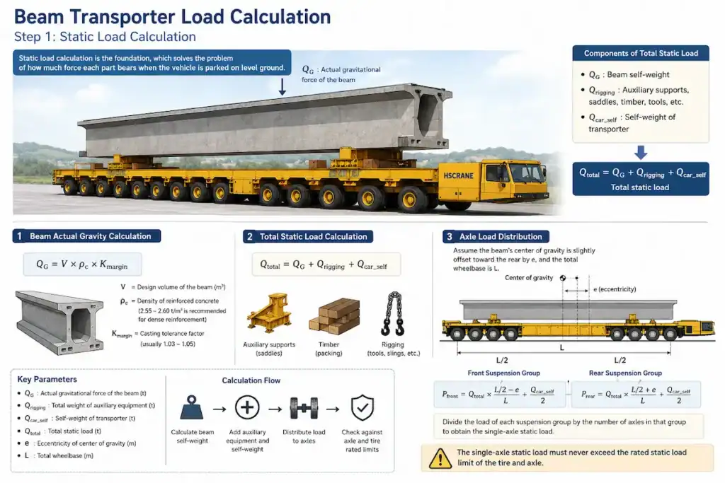
Static Load Calculation
This is the foundation. It solves the problem of “how much force each part bears when parked on flat ground.”
- Beam actual gravity: QG=V×ρc×Kmargin
- V is design volume (m³).
- ρc is reinforced concrete density (take 2.55−2.6t/m³ for dense rebar, not 2.4t/m³).
- Kmargin is pouring deviation factor (usually 1.03−1.05).
- Total static load: Qtotal=QG+Qrigging (Qrigging is total weight of auxiliary supports and spreaders).
- Axle load distribution: Assume beam center is offset toward the rear by e, and total axle span is L. The loads shared by front and rear suspension groups are:

Divide these by the number of axles in each group to get single-axle static load. This must not exceed the limit.
Dynamic Load Calculation
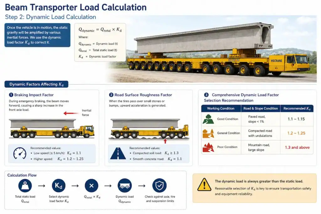
Once moving, static gravity is amplified by inertia. We use the dynamic load factor Kd to correct it:
Qdynamic=Qtotal×Kd is determined by these factors:
- Braking impact: During emergency stops, the beam pushes forward, increasing front axle load. Take 1.1 for low speeds (≤5km/h) and 1.2−1.25 for faster speeds.
- Road unevenness: Pits create upward acceleration. Recommend ≥1.3 for compacted soil roads; 1.1 for flat concrete.
- Selection recommendation:
- Excellent (paved, slope <1%): Kd=1.1−1.15
- Average (compacted, uneven): Kd=1.2−1.25
- Poor (mountainous, steep): Kd=1.3 or higher.
Center of Gravity and Stability Calculation
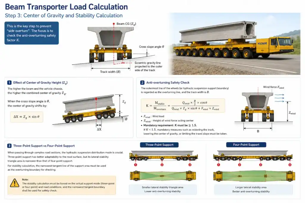
This is the key step to prevent rolling over. Focus on the anti-overturning safety factor K. The center of gravity height (Zg) impacts stability.
At cross slope angle θ, gravity offset is:

Anti-overturning safety check: Using the outermost wheel line (or suspension boundary) as the overturning line, with wheel track B:

- Fwind is wind load; Zwind is wind center height.
- Hard indicator: K must be ≥1.5. If K<1.5, you must widen the wheel track, lower the center of gravity, or restrict slope access.
- 3-point vs 4-point support: 3-point support adapts better but has a narrower lateral stability triangle. Stability calculations must use the narrowest tangent of the support area as the boundary.
Looking for a beam transporter solution for bridge engineering?
HSCRANE provides integrated solutions for custom beam transporters, bridge girder launchers, and beam lifting gantries from 5 to over 1000 tons. Our experienced heavy-load engineer team can perform professional dynamic load simulations and design based on your span, beam weight, slopes, and construction environment.
[Click here to get a free technical solution and custom quote immediately!]
How to ensure transport safety through load calculation?
Precise calculation ensures stability. Once you have the data, you must apply it to these five operational steps to manage transport risks:
- Select beam transporter tonnage rationally: Never choose equipment based on theoretical limits. Use the calculated maximum dynamic load (not static weight) and reserve a 15%-20% safety margin. This ensures the equipment handles unexpected stress easily.
- Avoid axle load overruns: Distribution is the core of load calculation. Use the results to set hydraulic suspension pressure. Ensure that on slopes or pits, single-axle loads are strictly within tire and roadbed limits. This prevents chain tire blowouts or road collapse.
- Control transport speed: Speed amplifies dynamic load. Based on the “braking impact coefficient” from your calculation, mandate maximum speeds for flat roads, descents, and turns. If the dynamic load factor is low, enforce low-speed crawling.
- Plan transport routes rationally: Survey the site with your calculated max cross and longitudinal slope limits. For road sections failing the anti-overturning safety factor (≥1.5), finish filling, widening, or hardening before the vehicle enters.
- Pre-departure load verification: Theoretical calculations fear field loading eccentricity. After the beam is placed, always verify the pressure of each support point using pressure gauges or weighing systems. Only sign off for departure after confirming it matches the theoretical distribution.
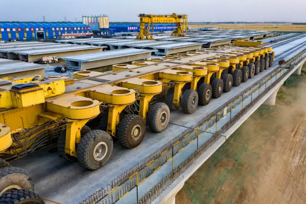
HSCRANE Beam Transporter Product Advantages
Heavy-load transport has no shortcuts. HSCRANE adheres to strict international standards. Our equipment structure complies with FEM 1.001 (3rd Edition). The fatigue life of key steel structures strictly follows EN 13001-3-1:2012, ensuring reliability under harsh conditions worldwide.
- 5-1000+ tons custom design: No “one-size-fits-all.” We provide 1-on-1 design for specific spans, weights, and transport limits, whether for box girders or T-beams.
- High-strength steel & FEA: The main frame uses high-yield-strength low-alloy steel. Before shipping, we perform stress distribution and fatigue life simulations using 3D FEA models to increase torsional rigidity.
- Multi-axle hydraulic steering: Standard heavy-duty dynamic balancing suspension ensures all-wheel contact on uneven roads. Supports crab steering, diagonal travel, and原地 turning for tight construction sites.
- PLC intelligent control: Industrial-grade PLC modules achieve microsecond speed synchronization and steering coordination for multi-vehicle transport, ensuring precise movement.
- Uzaktan teşhis: Equipped with online monitoring modules compliant with ISO 23815-1. Supports remote reading of key hydraulic and electrical data for quick troubleshooting.
- Complete bridge construction solutions: Our beam transporter communicates seamlessly with our bridge girder launchers and lifting gantries, providing an integrated “lifting, transport, and erection” solution.
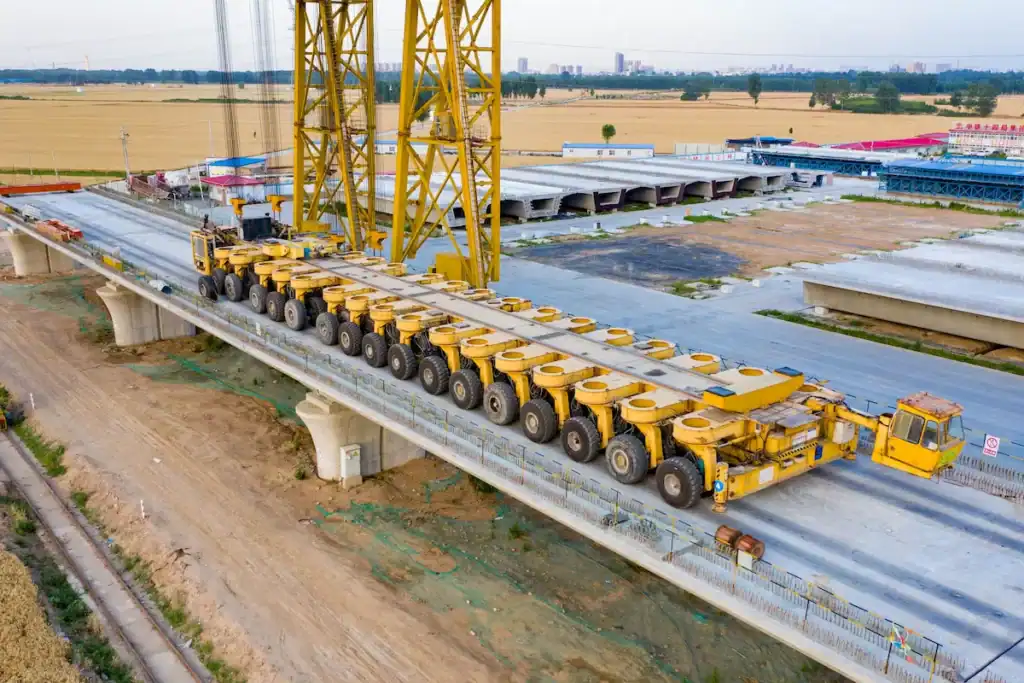
HSCRANE Classic Engineering Cases
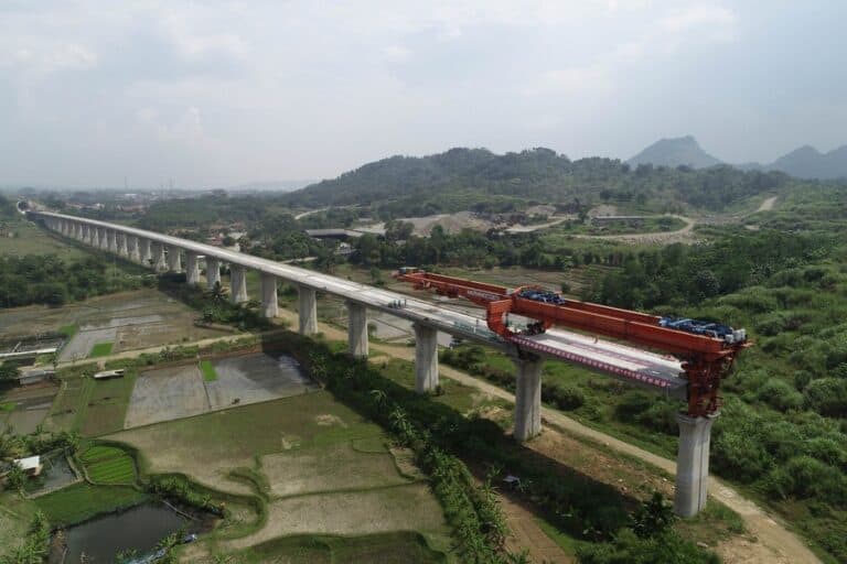
Case 1: Indonesia Jakarta-Bandung High-Speed Railway 900-ton Box Girder Transport
- Proje: SE Asia’s first 350km/h railway. High viaduct percentage and tropical rainforest climate challenged soil-bearing capacity.
- Challenge: PT Wijaya Karya (WIKA) needed to transport 900-ton, 32m beams over weak red clay roads using 4 sets of thousand-ton class beam transporters.
- Calculation: Engineers raised the dynamic impact coefficient to 1.35. Using a 64-axle double-link scheme, we strictly suppressed single-axle loads below 22 tons, far below the local road crushing threshold.
- Result: With dynamic compensation from the 4-point hydraulic support, the equipment suppressed offset impacts from pits, ensuring steady climbing on 3% slopes without sinking or slipping. The comprehensive transport cycle was shortened by 15%.
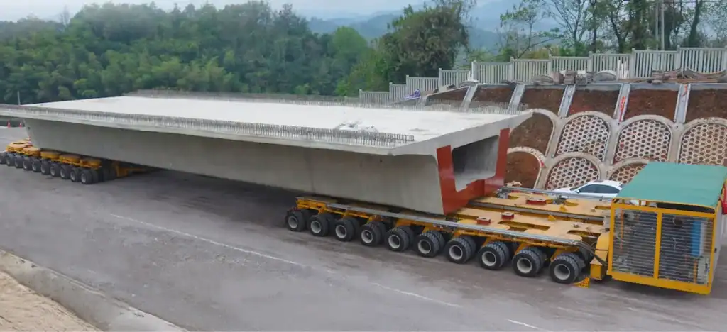
Case 2: Colombia Antioquia Mountain Bridge Project
- Challenge: Deep in the Andes, the project faced 6% long descents and hairpins with a 35m turning radius. Client needed to transport 160 T-beams (180 tons each).
- Solution: Simple mechanical brakes risk heat decay on long descents. HSCRANE delivered multi-axle equipment with high-power hydraulic retarders and independent braking circuits. We performed extreme anti-overturning analysis for “continuous braking + descent” conditions, locking the anti-overturning coefficient above 1.6.
- Result: All-wheel independent steering was critical for tight hairpins. Hydraulic suspensions maintained level support on unhardened gravel roads. All 160 T-beams were delivered zero-accident before the rainy season, proving absolute stability in extreme terrain.
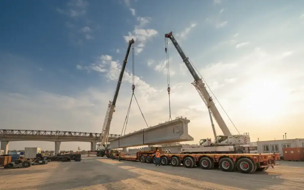
Common Errors and Prevention Methods in Beam Transporter Load Calculation
In heavy-load transport, tragic accidents often stem from “taking things for granted” during calculation. Here are the 5 biggest pitfalls and how to avoid them:
- Ignoring dynamic loads: The deadliest mistake is selecting equipment based on static states. Emergency braking or speed bumps cause instant load spikes.
- Prevention: Never use static weight alone. Always introduce a dynamic load coefficient (1.1-1.3) based on road conditions and speed.
- Center of gravity calculation errors: Assuming the center of gravity is at the geometric center is wrong. Thickened end diaphragms and asymmetric prestressed tendons shift it significantly.
- Prevention: Calculate 3D coordinates based on actual reinforcement drawings and cross-section changes. Never rely on rough volumes.
- Uneven axle load distribution: Dividing total weight by the number of axles ignores wheel “suspension” due to road unevenness.
- Prevention: Use a hydraulic suspension grouping model. Ensure pressure margins exist under max stroke to avoid “hard tops.”
- Exceeding foundation bearing capacity: Even if the transporter holds, soil may fail under high pressure, causing overturns.
- Prevention: Check tire ground contact pressure. If it exceeds geotechnical limits, install steel plates or replace foundation soil.
- Ignoring special conditions: Overlooking wind loads or harsh mountain curve combinations.
- Prevention: Force an “extreme stress model” including max wind, limit cross slope, and emergency braking.
Summary: Scientific Load Calculation Makes Bridge Transport Safer and More Efficient
Load calculation is not a formality; it is the only scientific basis for equipment selection. From chassis rigidity to hydraulic layout, every parameter reduces on-site risk. Comprehensive static/dynamic analysis and anti-overturning checks eliminate over 80% of lethal hazards before departure. For construction units, professional reliability outweighs hardware price. In thousand-ton heavy-load operations, safety is the greatest efficiency.
Are you looking for the right beam transporter?
Still struggling to match complex parameters? Leave it to us. HSCRANE’s senior heavy-load engineers provide free customized load calculation reports, equipment selection advice, and transport solutions based on your beam weight, span, and site environment. We help you cut off risks at the source and maximize transport efficiency.
[Contact us now for free consultation and exclusive solutions!]
Uzman Tavsiyesi:
Data accuracy is the prerequisite for equipment selection. Even the top-tier beam transporter cannot withstand an incorrect eccentric load calculation. Before finalizing tonnage, ask your engineering team to verify static/dynamic loads and anti-overturning safety factors.
[Click to learn more: Köprü İnşaat Ekipmanları Seçimi ve Maliyet Kontrolü Kılavuzu (2026)]
SSS
Q: Can I buy an 800-ton capacity beam transporter for an 800-ton box girder?
A: Absolutely not. 800 tons is the static weight. Actual transport involves braking and road bumps. We recommend a 15%-20% safety margin. For an 800-ton beam, use 900-1000 ton equipment to prevent long-term fatigue in the chassis and hydraulic systems.
Q: How does load calculation differ for routes with sharp turns and slopes?
A: Models become complex. Normal flat roads only need static load analysis. Slopes and sharp turns require “lateral and longitudinal load transfer” calculations. HSCRANE uses 3D simulations to calculate center-of-gravity shifts, adjusting wheel tracks and suspension layouts accordingly to keep the anti-overturning factor above 1.5.
Q: How long does it take for HSCRANE to provide a plan?
A: After you provide complete drawings (or dimensions/weight) and route parameters (max slope, turn radius), our team typically provides a preliminary mechanical calculation and configuration draft within 24-48 hours.
Bu belge yalnızca referans amaçlıdır. Belirli işlemler, yerel yasa ve yönetmeliklere ve ekipman kılavuzlarına kesinlikle uygun olmalıdır.

Köprü Projeniz İçin Uzman Tavsiyesi Alın
Mühendislik ekibimiz köprü inşaat ekipmanları konusunda onlarca yıllık deneyime sahiptir. Doğru çözümü bulmanıza yardımcı olalım.
 Sohbet etmek için tarayın