 EN_US
EN_US  Español
  Русский
  العربية
  Português do Brasil
  Français
  Bahasa Indonesia
  Türkçe
  Tiếng Việt
  Bahasa Melayu
  Українська
 Technical Insight
Technical Insight
Bridge Girder Launcher Construction Process: Erection & Span Passing
Overview
This article analyzes the bridge girder launcher in modern road projects. We focus on girder lifting, positioning, and hole-passing operations. We showcase stability in complex conditions using HSCRANE technology. The content covers the full construction process. This includes standardized procedures from lifting to precise positioning. We detail hole-passing technical points and center of gravity control. This ensures safe cross-hole movement and load conversion. HSCRANE features intelligent synchronous control and high-redundancy structures. These systems effectively solve girder swing and unbalanced load risks. Our customized solutions meet ISO and FEM standards. They improve construction precision and efficiency for global bridge projects.
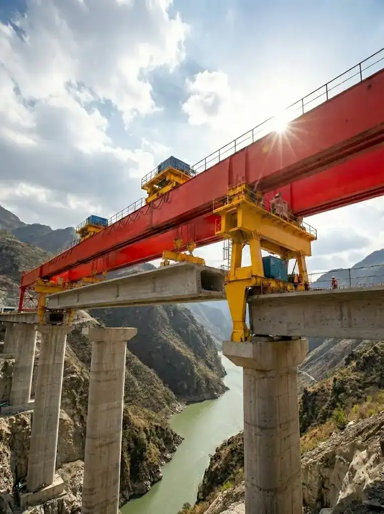
In modern viaduct and high-speed railway construction, the bridge girder launcher is more than just a lifting tool—it determines your project timeline and safety baseline. A single failure during the span-passing phase or a millimeter misalignment in girder erection can lead to catastrophic delays. This comprehensive guide breaks down the critical construction processes, from precise girder positioning to high-risk cantilever span passing, showing how advanced control systems can mitigate risks in complex environments.
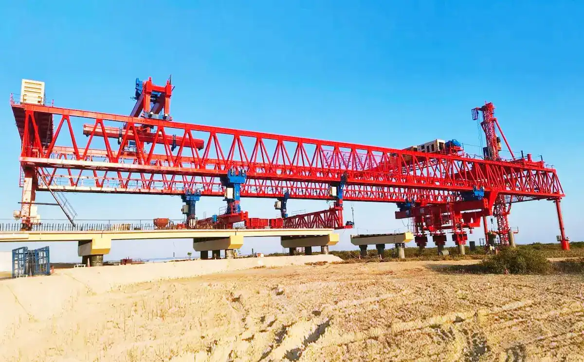
Overview of the Bridge Girder Launcher Workflow
Bridge girder launcher operations are high-risk and require strict precision. The core process cycles through installation, girder placement, and hole-passing.
Construction Preparation Stage
- Site Survey and Rail Laying:We must strictly check roadbed capacity and abutment flatness. Rail laying requires millimeter-level control for parallelism and elevation. This prevents the bridge girder launcher from shifting during heavy loads.
- Installation and Commissioning:We assemble the main girder, legs, and electrical systems in sequence. After installation, we perform no-load, static, and dynamic load tests. We focus on verifying hydraulic legs and traveling mechanisms.
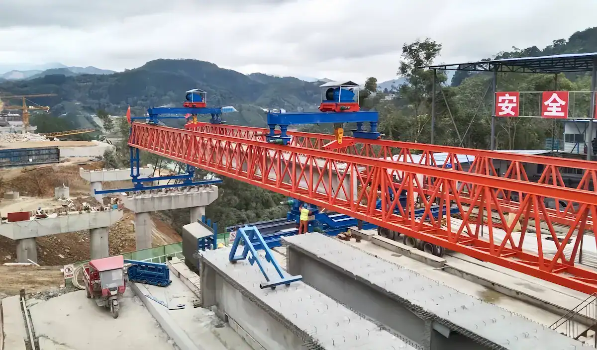
Girder Construction Process
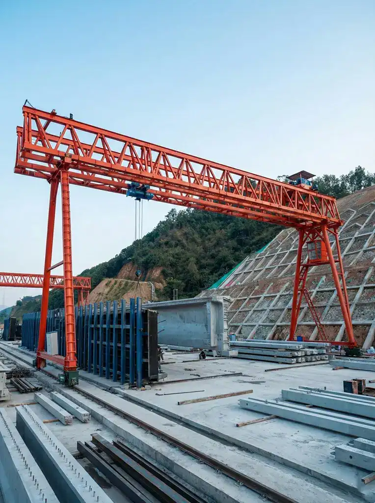
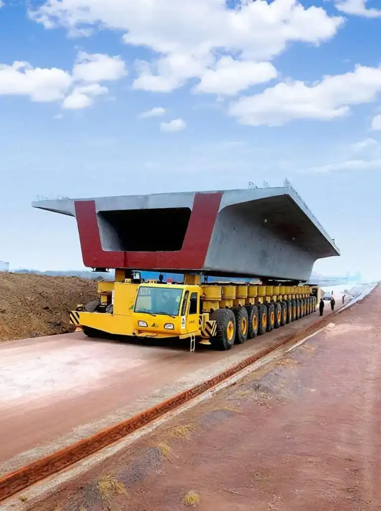
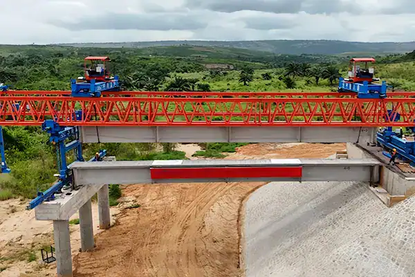
- Lifting and Feeding:A transport vehicle delivers the prefabricated girder to the rear. The trolley lowers the spreader to lift the girder smoothly. We use frequency conversion technology for synchronized control. The trolley then carries the girder forward to the span.
- Lifting and Positioning:We perform longitudinal and transverse micro-adjustments before placement. HSCRANE equipment supports micro-slow speed control for accuracy. This ensures the girder aligns perfectly with the bearing centerline. We maintain a constant falling speed to avoid impacts.
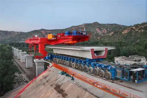
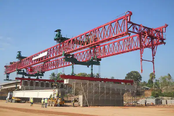
Hole-Passing Process
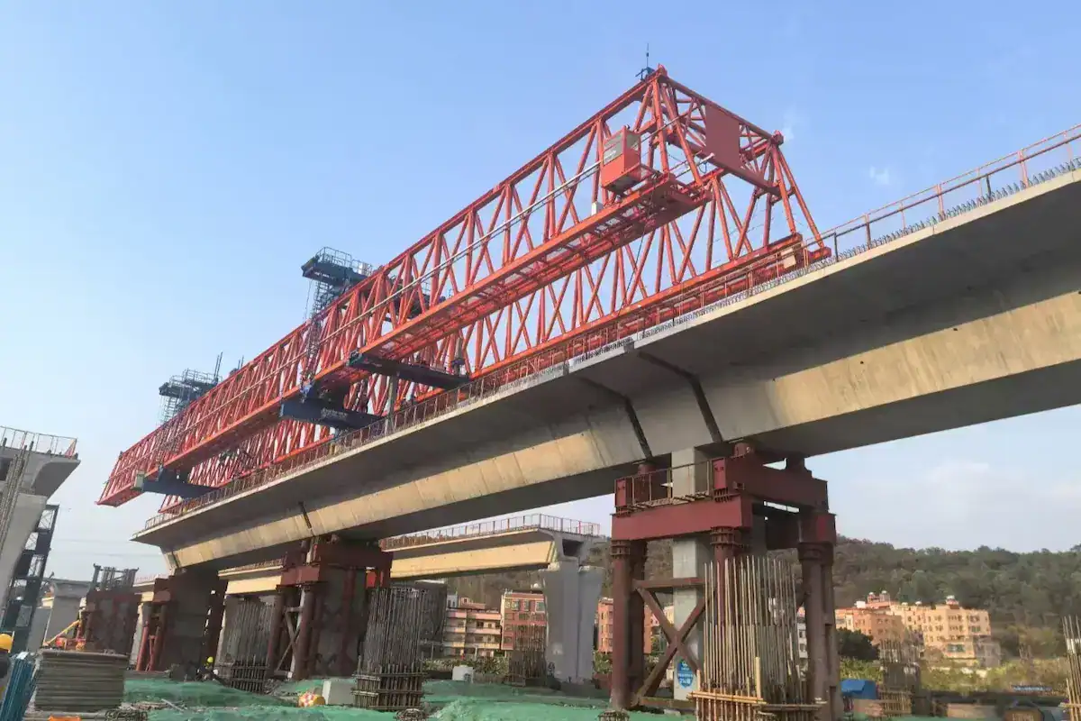
- Front Leg Conversion:We move the front leg to the next pier after finishing a span. This process involves converting the equipment’s stress points. We must lock the middle and rear legs. This maintains structural balance during the cantilever state.
- Whole Machine Forward Movement:The bridge girder launcher advances slowly along the rails using its drive system. We monitor longitudinal slope and wind interference in real-time. The cycle completes when the front leg lands on the next support stone.
Key Techniques for Girder Erection and Positioning
Successful bridge construction depends on precise control of static loads and dynamic displacement. Below are the core technical management dimensions during the process.
Girder Lifting and Positioning Technology
- Lifting Stability Control:We use dual lifting point synchronous technology. The PLC closed-loop system monitors load distribution in real-time. This ensures the girder remains level during the lifting process. It avoids uneven stress on the bridge girder launcher caused by gravity shifts.
- Precise Alignment Methods:We combine laser pointers with mechanical limit devices. Switch to “inching” mode when the girder is 10-20cm above the bearing. The trolley’s micro-adjustment mechanism achieves millimeter-level centerline alignment.
- Anti-Sway Measures:Spreaders feature a flexible compensation system and electronic anti-sway algorithms. This cancels out inertial swings from starting or braking. It ensures the girder remains stationary or quasi-stationary in the air.
Bridge Girder Launcher Operation Control
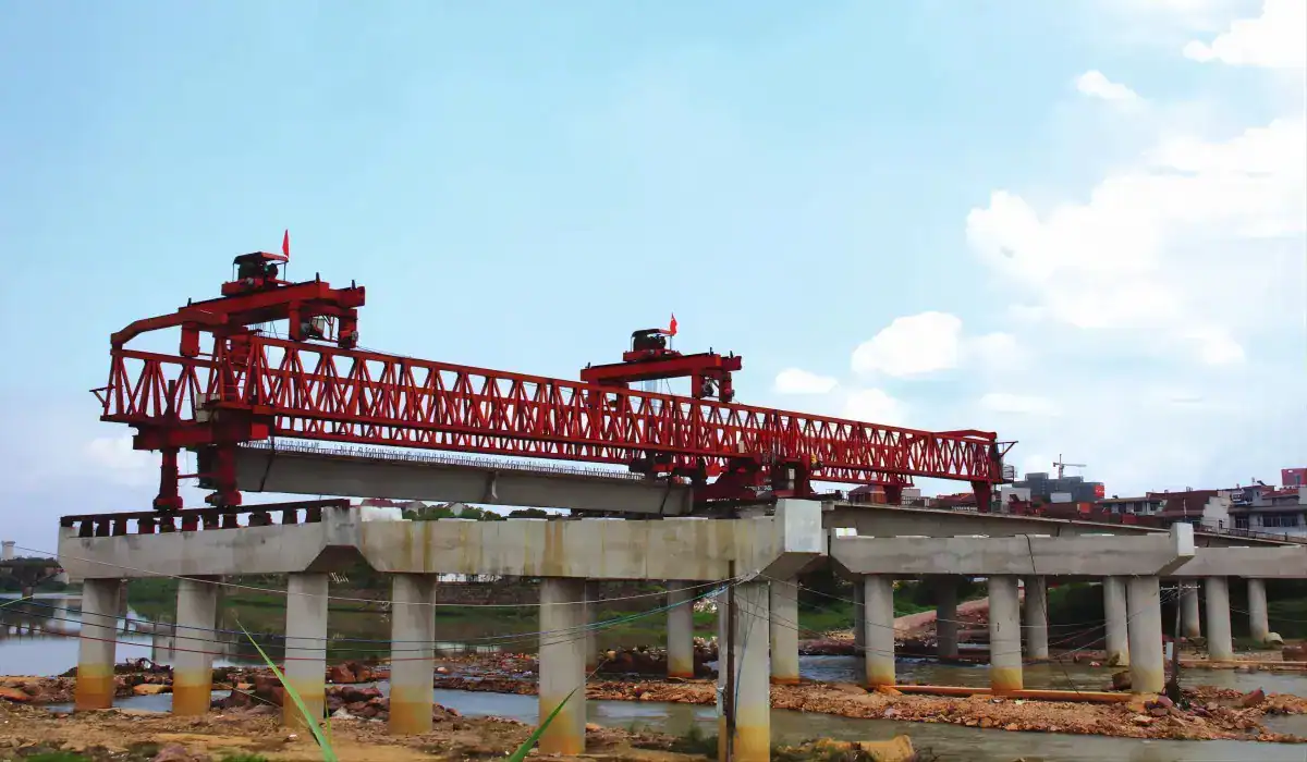
- Synchronous Control Technology:HSCRANE equipment uses Variable Frequency Drives (VFD). This allows for zero-speed braking and smooth acceleration. Multiple drive units synchronize via bus communication to prevent body skewing.
- Rail Precision Requirements:Rail joint height differences must not exceed 1mm. The gap between rails must be less than 2mm. This ensures the machine runs on a solid surface to prevent instability.
- Environmental Control:The construction site must have real-time wind speed monitoring. Stop lifting operations if wind speeds exceed 13.8m/s. Perform hole-passing tasks only when wind speeds are below 9m/s. Always use hydraulic rail clamps and windproof cables.
Erection Precision Control
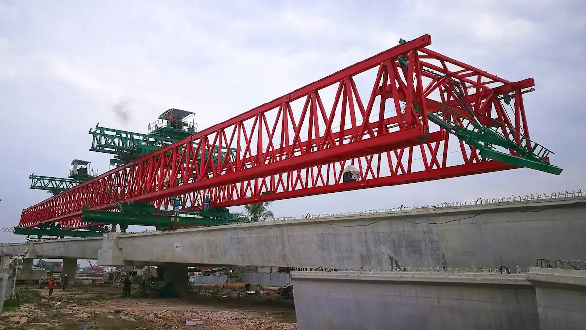
- Centerline and Elevation Control:Check pier centerline and stone elevation before erection. Use a total station to track the coordinates of the four girder corners. This ensures the finished bridge deck matches the design parameters.
- Bearing Installation Accuracy:The bearing base plate must fit tightly with the support stone. Use gravity grouting to ensure even stress distribution. This prevents uneven settlement or bearing gaps in the future.
- Common Errors and Adjustments:
- Longitudinal Displacement:Solve this by adjusting the trolley limits.
- Elevation Limits:Use stainless steel leveling plates for fine compensation.
- Angular Torsion:Use hydraulic jacks on the legs for local lifting corrections.
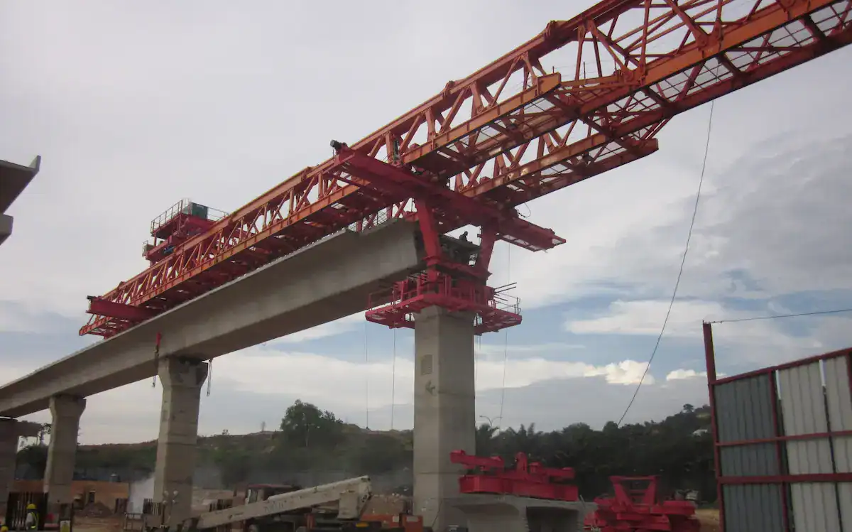
Span Passing Techniques (Crucial Operations)
Hole-passing is the most dangerous stage in bridge girder launcher construction. It involves moving the center of gravity from a completed span to a cantilevered position.
Hole-Passing Principles and Steps
- Center of Gravity Analysis:Initially, the gravity center stays between the rear and middle legs. As the main girder extends forward, the center shifts toward the middle leg. HSCRANE uses lightweight, high-rigidity designs to reduce cantilever deflection effectively.
- Leg Load Conversion:This process transitions from multi-point support to cantilevered operation and relocation. The hydraulic system must ensure even load distribution on the middle legs. Unilateral loading is strictly prohibited.
- Machine Advancement Flow:
- Retract front legs and advance the main girder via cantilever.
- Position front legs on the next pier or abutment.
- Release rear legs and move the entire machine forward.
Hole-Passing Stability Control
The anti-overturning stability coefficient during hole-passing must exceed 1.5.
Stability Item | Technical Requirement | Description |
Anti-overturning | Counterweights or rear leg hooks | Offsets the overturning moment from the large cantilever. |
Structural Balance | Real-time load monitoring | Ensures the stress deviation between girders is le 5%. |
Temporary Support | Auxiliary support cylinders | Provides hard support to prevent hydraulic creeping. |
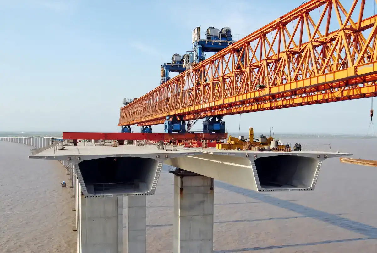
Risks and Responses During Hole-Passing
Environmental factors greatly affect hole-passing operations. You must strictly monitor the following risk parameters:
Risk Point | Monitoring Parameter | Response Measure |
Wind Impact | Instant speed > 9 m/s | Stop immediately and anchor the machine with rail clamps. |
Rail Deviation | Slope > 1% or gauge error > 5 mm | Recalibrate transverse rods and reinforce the foundation. |
Offset Risk | Leg pressure difference > 10% | Check hydraulic synchronization and adjust trolley balance. |
- Emergency Handling:If power fails during hole-passing, enable manual hydraulic brakes and mechanical pins. Never leave the main girder in a cantilever state for long.
- Monitoring Points:Assign personnel to watch the front and middle leg drive units. Use a total station to monitor main girder deflection in real-time. Stop if deflection exceeds L/400 (L = cantilever length) to check welds.
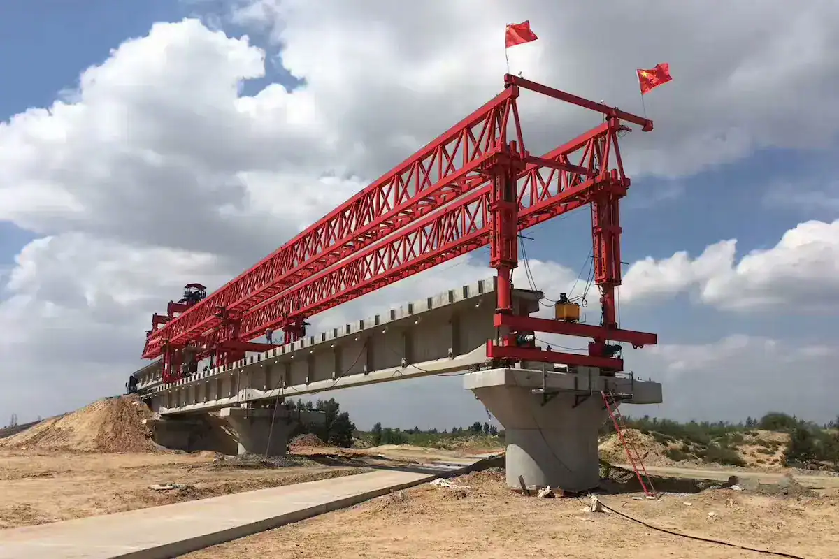
Bridge Girder Launcher Safety Management
As heavy lifting equipment, the bridge girder launcher requires a “safety first” approach. A comprehensive protection system is mandatory for all projects.
- Pre-operation Inspection:Perform these five mandatory checks daily before starting:
- Tightness of all main girder connection bolts.
- Hydraulic system seals and oil pressure values.
- Wire rope wear and lubrication status.
- Electrical system grounding protection.
- Sensitivity of all limit switches. %%GB1%%
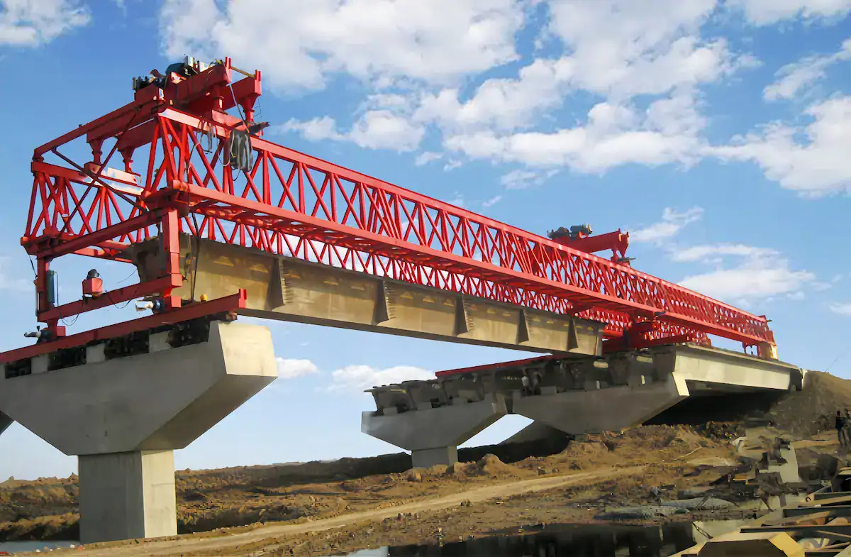
HSCRANE Custom Solutions & Global Case Studies
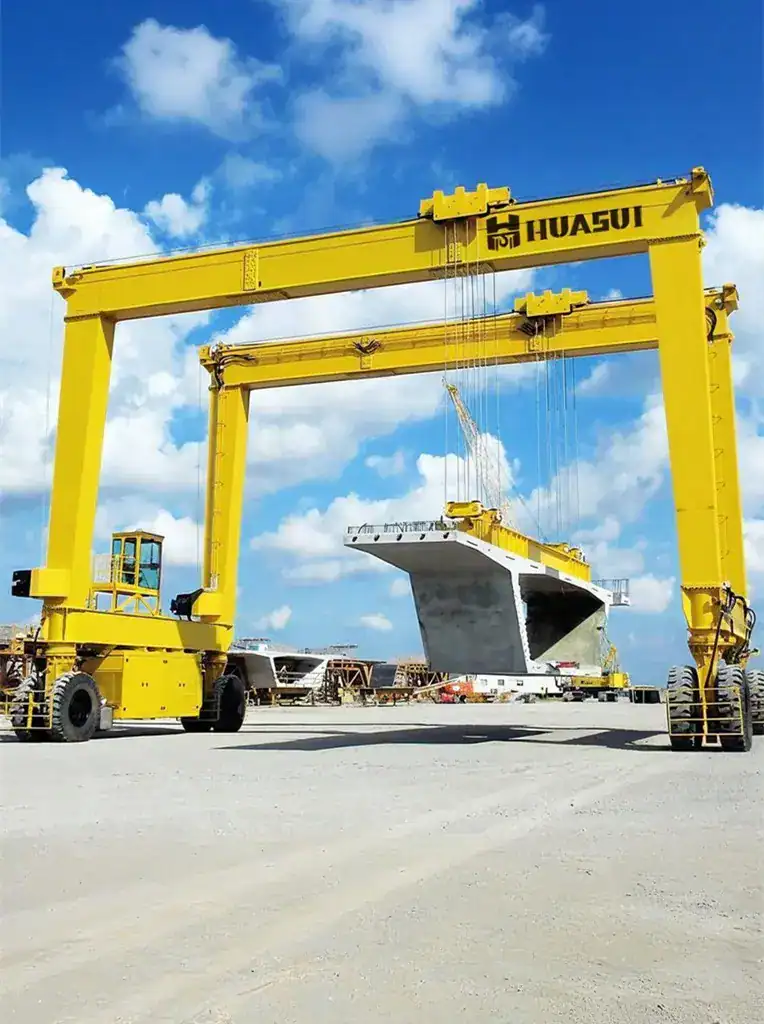
As a leading global supplier, HSCRANE provides high-performance bridge girder launcher equipment. Our machines lead the industry in rigidity, intelligence, and safety.
- High Stability Structural Design:We use optimized box-type main girders and truss structures. This reduces self-weight while greatly increasing torsional stiffness. Finite Element Analysis (FEA) ensures minimal deflection during cantilever hole-passing.
- Intelligent Control Systems:We integrate PLC closed-loop control and digital load monitoring. Exclusive multi-point hydraulic synchronization keeps errors within pm 2 mm. The system supports remote diagnostics and real-time data recording.
- Safety Performance Guarantee:Our equipment follows ISO, FEM, and CE international standards. We include redundant safety mechanisms like hydraulic locks and anti-sway systems. Every unit undergoes strict simulated condition testing before delivery.
- Customized Solutions:We provide non-standard customization for small-radius curves and steep slopes. HSCRANE offers specific hardware and algorithms for extreme climates or altitudes. We adapt to any unique project requirement effectively.
- Global Project Experience:HSCRANE has extensive experience from Ecuador to the Aegean Sea. Our engineers provide full on-site support for installation and training. We ensure high-efficiency service in diverse regional markets worldwide.
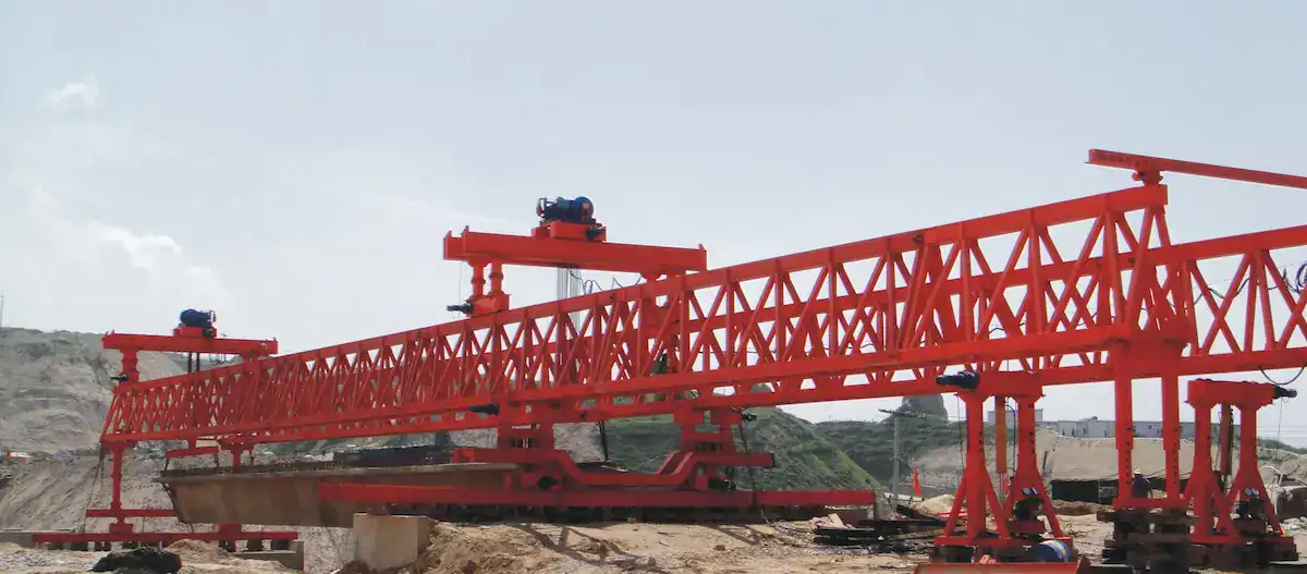
HSCRANE Bridge Girder Launcher Classic Cases
Philippine Inter-island Highway Project
HSCRANE provided a customized 120-ton bridge girder launcher for this project. The equipment showed high adaptability to salt spray and strong gusts.
- Project Challenges:The bridge featured small-radius curves (R < 400 m) and constant sea winds.
- Technical Application:We installed reinforced windproof anchor systems and anti-corrosion coatings. Adjustable main girders allowed for smooth feeding on curved sections.
- Results:No structural deformation occurred during construction. Installation efficiency increased by 20% compared to traditional local equipment.
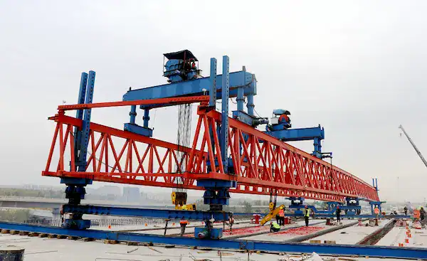
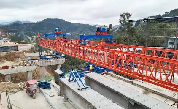
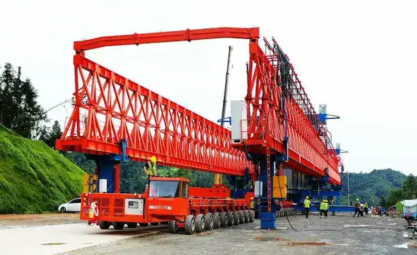
Vietnam High-Speed Rail 180T Application
This key project required 180-ton heavy lifting with very short hole-passing cycles.
- Technical Highlights:We utilized the HSCRANE full hydraulic automatic hole-passing system. This reduced the transition time from 6 hours to under 1.5 hours.
- Precision Control:High-speed rail requires strict elevation and axis accuracy (pm 1 mm). We used full closed-loop frequency control for steady girder placement.
- Value Realization:High automation reduced on-site manual labor by 30%. It ensured absolute safety for heavy girders during continuous high-altitude operations.
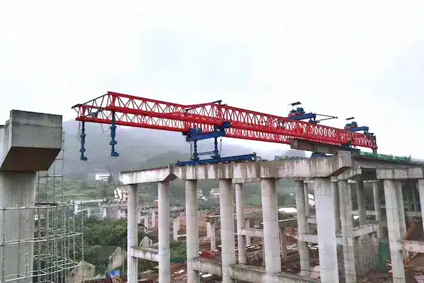
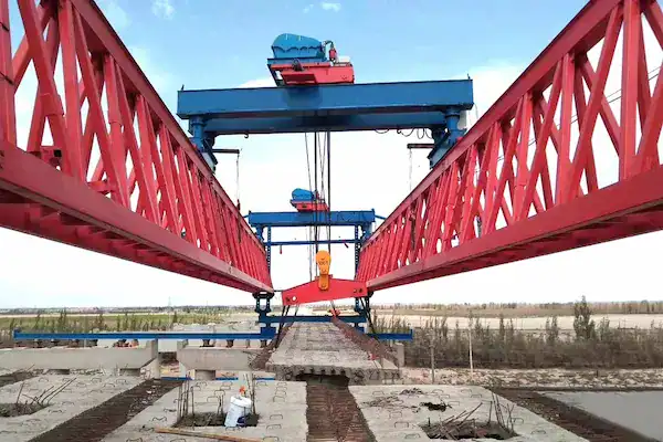
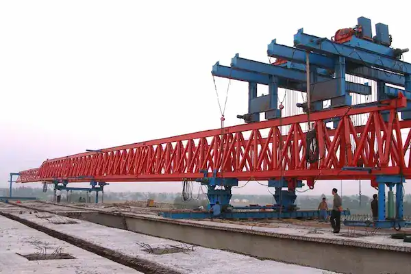
The bridge erection and hole-passing process defines the success of upper bridge construction. It directly impacts equipment stability, installation precision, and the overall project timeline. Controlling load balance and environmental factors is vital for safety and efficiency. High-quality equipment offers better structural rigidity and intelligent systems. These features handle complex conditions like high piers and long spans. They minimize downtime and ensure high construction quality.
Need Engineering Support for Your Next Bridge Project?
Complex terrains and heavy girder loads require more than standard equipment—they require tailored engineering. Whether you need a 180T launcher for a high-speed railway or a custom gantry for a coastal bridge with high wind loads, HSCRANE’s technical team is ready to assist.
[Contact Our Engineers on WhatsApp]
FAQ
Here are professional answers to common technical questions regarding bridge girder launcher operations and selection:
Q1: How do you prevent overturning during hole-passing?
A1: We use anti-hook devices and hydraulic locks for balance. Counterweights are placed on the main girder. Ensure an anti-overturning coefficient ge 1.5. Stop work during high winds or on unstable ground.
Q2: How do you solve "positioning deviation" when placing girders?
A2: PLC closed-loop systems allow for micron-level adjustments. Anti-sway algorithms ensure precise alignment with the bearing. This eliminates errors from wind or movement. It guarantees perfect girder placement every time.
Q3: How does HSCRANE adapt to curves and slopes?
A3: We provide custom adjustable rods and rotating legs. These features support curve radii under 400m. Automatic hydraulic leveling keeps the machine stable. It handles steep bridge gradients safely and smoothly.
This document is for reference only. Specific operations must strictly comply with local laws and regulations and equipment manuals.

Get Expert Advice for Your Bridge Project
Our engineering team brings decades of experience in bridge construction equipment. Let us help you find the right solution.

 Scan to chat