 EN_US
EN_US  Español
  Русский
  العربية
  Português do Brasil
  Français
  Bahasa Indonesia
  Türkçe
  Tiếng Việt
  Bahasa Melayu
  Українська
 Technical Insight
Technical Insight
Selecting a Bridge LaunchingGantry System: 7 Critical Factors Engineers Must Evaluate
Overview
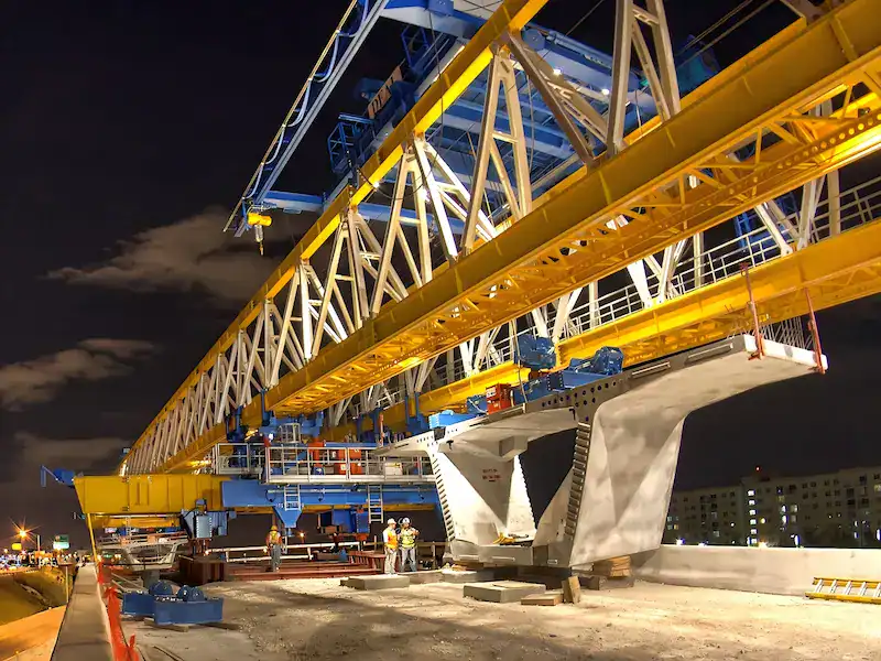
On a bridge construction site, a bridge launching gantry is absolutely the “behemoth”. It determines the life or death of a project. Choosing the right equipment ensures the schedule and safety. A wrong choice brings frequent downtime for maintenance. It causes budget overruns or even irreversible safety accidents. Many construction enterprises fall into misunderstandings during selection. They only look at the price or blindly pursue large tonnage. In fact, selecting a bridge launching gantry is a complex systems engineering task. This article does not discuss empty theories. It starts from frontline engineering practice. We rigorously analyze the 7 core dimensions for engineers.
These must be evaluated during proposal comparison. This includes basic beam parameter calculations and severe onsite terrain constraints. It also includes easily overlooked operating costs and the manufacturer’s technical heritage. We hope this practical guide helps you avoid hidden traps. It can help you make a safe, cost-effective scientific decision.
Good preparation foretells a successful job:
Bridge construction offers no opportunities for trial and error. One wrong step in selection costs millions for onsite adjustments. If you currently have an ongoing project, please spend 5 minutes. Check the 7 dimensions below to ensure your equipment is stable. Want to get a ready-made configuration sheet directly? You can contact our onsite engineers at any time. Send them your span and working conditions. They will directly provide customized drawings and quotes.
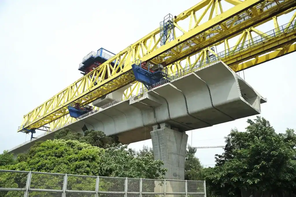
Determine Capacity of Bridge Launching Gantry Based on Bridge Parameters
Before discussing complex control systems or fancy functions, calculate a “hard bill”. This refers to bridge parameters and load capacity. Selecting a bridge launching gantry without beam data is armchair generalship. When onsite engineers perform initial selection, these core indicators come first.
Why Load Capacity is the Primary Factor in Selection
- Impact of bridge span on equipment selection: Many buyers think span only determines the main girder’s length. Actually, wider spans test structural safety during “hole-passing” (self-displacing). It tests the anti-overturning moment and main girder’s deflection changes. A 10-meter span increase raises overall steel structure stiffness requirements exponentially.
- Requirements of beam weight on equipment configuration: A single prefabricated box beam can weigh up to 900 tons. You cannot choose equipment with exactly a 900-ton rated capacity. The beam’s center of gravity deviation requires attention. Specific lifting point locations also require redundancy in hoisting mechanisms. The bridge launching gantry needs sufficient redundancy in trolley configuration.
- Importance of construction conditions and safety margins: Construction sites never have 100% ideal working conditions. Operator errors or dynamic load impacts can occur. Strong side winds can also instantly exceed the theoretical load. Leaving sufficient safety margins buys “error tolerance” for complex conditions.
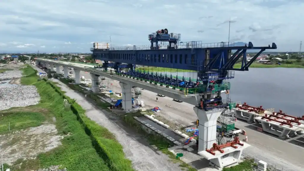
Core Technical Parameters to be Calculated
Do not just look at numbers on the manufacturer’s brochure. Engineers must personally verify these core data during proposal review:
- Maximum beam weight and safety factor calculation: The basic formula is very simple. However, never forget to add the dynamic load coefficient. During lifting, the force greatly exceeds the static weight. Usually, the lifting dynamic load coefficient ranges from 1.15 to 1.25.
- How to determine rated lifting capacity of the equipment: True rated lifting capacity involves multiple weight factors. Add the heaviest single beam, lifting appliances, wire ropes, and rigging. Multiply this total by the onsite harsh condition coefficient. If working conditions require frequent asymmetric biased loading, adjust this upward.
- Construction additional loads: This is the most easily overlooked part. Wind load is a massive variable in canyons or coastal areas. Equipment braking inertial forces must also be considered. Gradient additional forces from uneven track laying are also important. All these must enter the overall load capacity verification model.
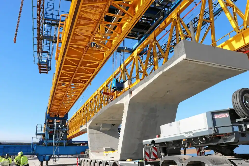
Suitable Bridge Launching Gantries for Different Spans
To match requirements intuitively, we summarized recommended configuration solutions. These cover the three most common span ranges in engineering:
| Bridge Span Characteristics | Recommended Gantry Type | Core Configuration Considerations | Applicable Onsite Conditions |
| Small Span (<30 meters) | Single girder or light double girder bridge launching gantry. | Emphasize mobility and assembly speed. Self-weight requires lightweight design. This reduces compressive stress on bridge piers. | Urban overpasses and common sections of highways. Construction sites with narrow areas. |
| Medium/Large Span (30-50m+) | Truss type double girder or segmental assembly bridge launching gantry. | High stiffness main girders are mandatory. Trolleys need micro-movement adjustment. Auxiliary legs prevent overturning when passing holes. | High-speed railway passenger lines. Cross-river and cross-sea large bridges. Heavy-haul railway bridges. |
| Curved or Special-shaped Bridge | Variable span self-balancing bridge launching gantry. | Front legs need lateral movement and angle rotation. The overall center of gravity supports dynamic leveling. | Ramp bridges and mountain bridges with large curvature radius. Bridges with large cross slopes. |
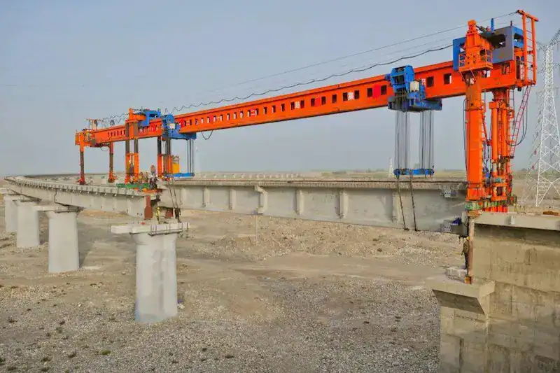
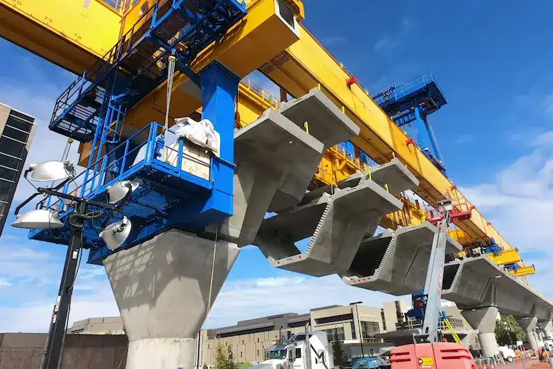
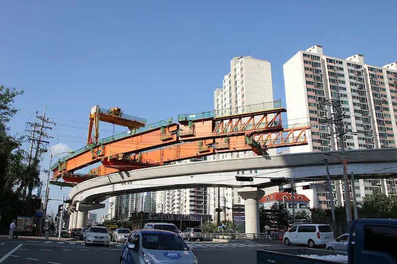
Case Analysis: Customized Gantry Solution for Curved Bridge Project
Discussing theory is not as good as actual combat. Last year, HSBRIDGE handled a mountain highway interchange ramp project. We encountered an extreme curved bridge. It had a minimum curve radius of 60 meters. It also featured a large cross slope of 4%. Using a conventional straight bridge launching gantry is dangerous. Front legs could not land accurately on piers when passing holes. Forced erection easily causes equipment to derail or overturn.
How did our engineering team break the deadlock?
We did not blindly increase the equipment tonnage. Instead, we performed customized modifications on the equipment “joints”:
- Modification of front legs: We equipped front legs with large-stroke hydraulic lateral movement mechanisms. They achieve a maximum lateral adjustment range of 2.5 meters. This adapts to the curve slope perfectly.
- Three-dimensional micro-adjustment trolley: We upgraded the lifting trolley. We added a rotational micro-adjustment function within the lifting plane. The beam body precisely fits the designed curve when dropping. This avoids high-risk manual pulling and dragging in midair.
Evaluate Construction Site Conditions and Transportation Restrictions Thoroughly
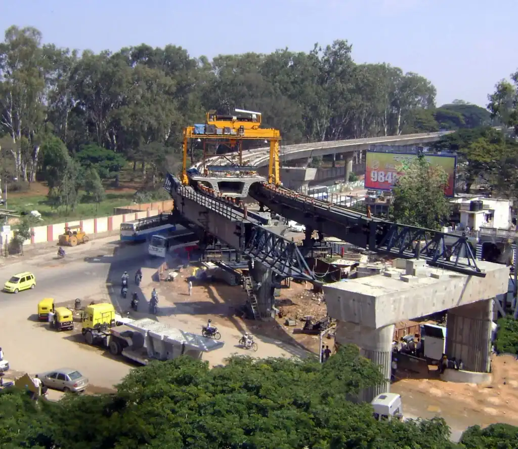
Looking at parameters on CAD drawings in the office makes every bridge launching gantry look perfect. However, once you arrive at a muddy, narrow, and uncertain construction site, things change completely. The onsite environment and logistics conditions often hold “veto power” over the final equipment selection.
Why Onsite Environments Affect Equipment Selection
Many times, what drags down project progress is not equipment failure. It is the equipment’s inability to adapt to local conditions.
- Site conditions directly determine construction efficiency: No matter how advanced a bridge launching gantry is, it slows down without enough operating radius and hole-passing space. For example, when working under dense high-voltage grids or close to existing buildings, choosing a model with oversized dimensions or severe movement interference means onsite engineers spend most of their day avoiding obstacles.
- Analysis of a common selection mistake: We once took over a rescue project that required a mid-way equipment replacement. The previous subcontractor blindly purchased an oversized double girder bridge launching gantry to pursue single-erection efficiency. However, because the turning radius of the temporary construction road was extremely small, several ultra-long flatbed trailers could not enter the site at all. In the end, they spent over half a month blasting mountains to widen the road. The hidden costs for early entry alone exceeded budget by nearly a million.
Typical Terrain Condition Evaluation
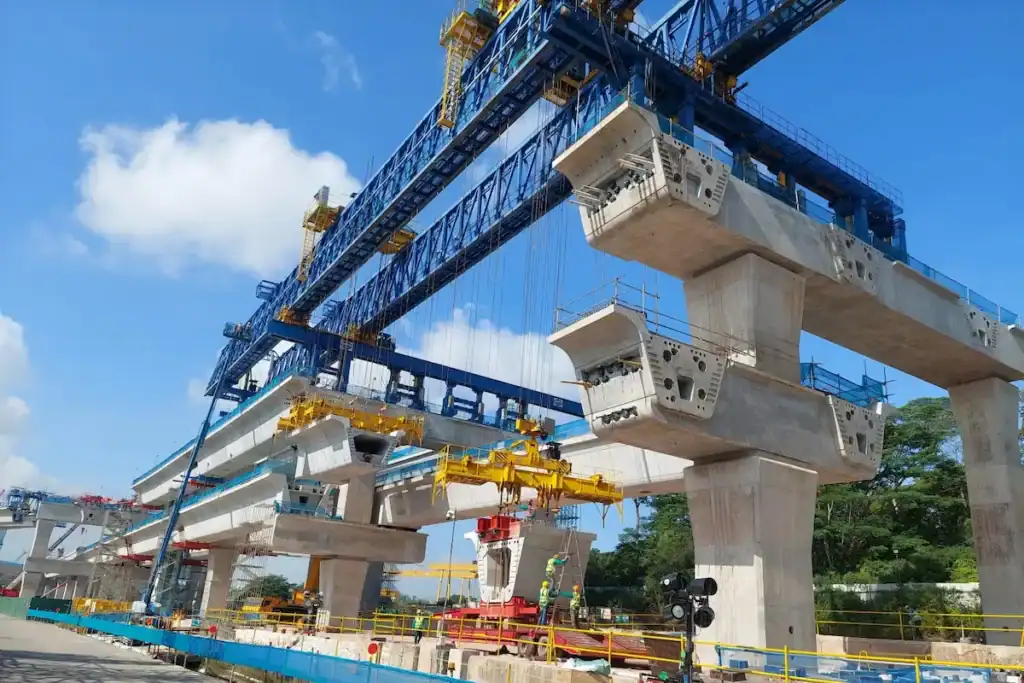
Different terrains pose completely different requirements for wind resistance, ground bearing pressure, and mobility. During onsite surveys, we usually focus on evaluating the following environmental pain points:
| Construction Terrain Features | Maximum Onsite Risks and Challenges | Core Selection Requirements |
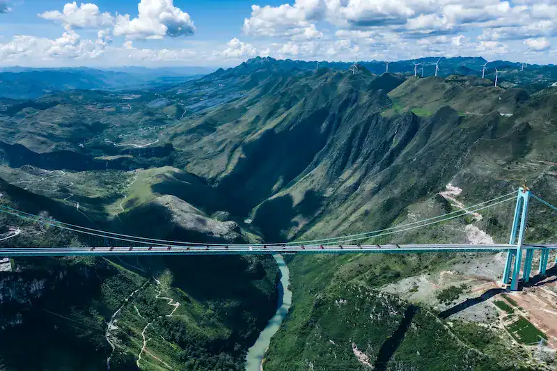
| Mountain / High-Altitude Bridges | Valley wind is extremely strong with sudden gusts. Longitudinal and cross slopes are steep. The working face is extremely narrow. | High wind resistance rating and anti-slip rolling design are mandatory. Low overall center of gravity is required. Strong climbing and self-balancing capabilities are preferred. |
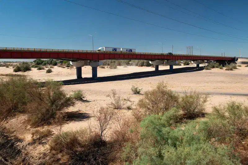
| River Valley / Tidal Flat Bridges | The water table is high and soil is soft. Large temperature differences between day and night cause equipment condensation and slipping. | Strictly control the overall self-weight. Large stiffness of the main girder is required. The deflection of the front leg extension distance during hole-passing must stay within a safe range. |
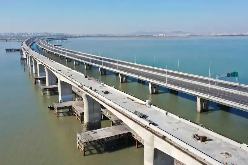
| Cross-River / Cross-Sea Large Bridges | Salt spray corrosion is severe. High-altitude operation risks are extremely large. There are no leverage points on the water. | High-level anti-corrosion coatings (such as C5-M level) are needed. An excellent anti-sway control system for the hoisting mechanism is required to ensure stable beam lowering. |
Foundation Bearing Capacity Analysis
The self-weight of a bridge launching gantry plus the beam weight totals hundreds of tons. This weight ultimately presses down on a few legs. If the foundation does not provide enough support, the strong upper structure becomes a castle in the air.
- Leg arrangement and ground bearing pressure: Onsite engineers must verify the grounding area of the legs. If ground bearing capacity is insufficient, choose equipment with larger pressure-bearing pads or crawler-type travel mechanisms. This distributes compressive stress and prevents fatal leg sinking.
- Strict requirements for track laying: For wheel-rail type bridge launching gantries, track flatness is the lifeline. If site conditions cause uneven settlement, track jamming or even overturning can easily occur during hole-passing.
- Weighing foundation reinforcement solutions: If soft foundations are detected, you must either spend heavily on piling and laying thick steel plates for reinforcement, or modify selection at the source. This means choosing a lightweight bridge launching gantry with lighter self-weight and lower wheel pressure. This is a critical cost trade-off.
Transportation and Onsite Assembly Difficulty
Logistics transportation and onsite assembly are the most easily ignored blind spots in selection planning.
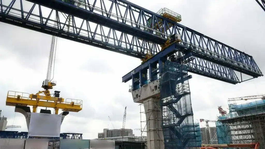
- Transportation restrictions for urban bridge projects: Municipal projects often come with strict height, weight, and night transportation restrictions. This requires the bridge launching gantry to have excellent modular disassembly capabilities. Individual component dimensions must never exceed urban oversize transportation standards.
- Transportation challenges for remote area projects: Mountain mudslides frequently wash away temporary roads. If individual equipment modules are too heavy for conventional trailers, the cost of using specialized multi-axle transport vehicles will be skyrocketing.
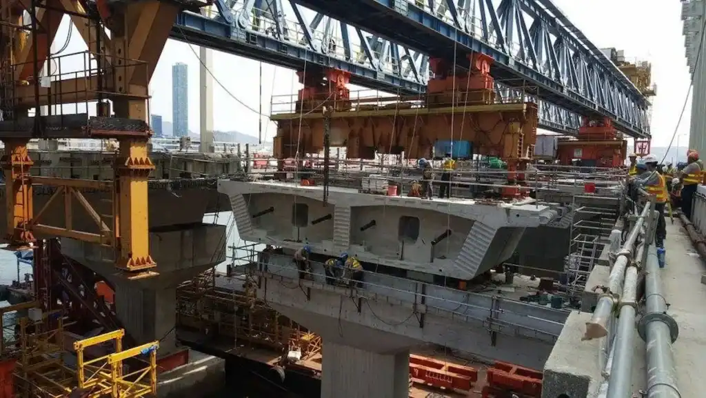
- Onsite assembly space requirements: A bridge launching gantry with a 50-meter span requires a flat site at least the size of a football field on the ground to assemble the main girder. If such a large open space is unavailable (such as assembling directly on a roadbed or at a tunnel entrance), choose a model that supports in-situ segmental assembly or aerial cantilever assembly designs.
Configuration Recommendations for Different Working Conditions
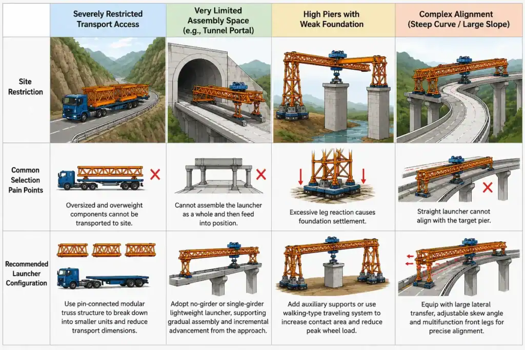
To address the complex onsite restrictions mentioned above, we summarized this practical selection configuration strategy for engineers:
| Main Onsite Restricting Factors | Common Selection Pain Points | Recommended Configuration Direction |
| Highly Restricted Transport Roads | Ultra-long and ultra-wide components cannot enter the site. | Choose a modular truss structure with pin connections. Break the whole into parts to reduce individual transport dimensions. |
| Narrow Assembly Site (e.g., Tunnel Entrance) | Cannot perform overall assembly before feeding the machine. | Choose a lightweight gantry with a single girder or no launching girder. This supports gradual assembly and advancement on the bridgehead roadbed. |
| High Piers and Weak Foundations | Excessive leg reaction forces cause foundation settlement. | Add auxiliary supports or adopt a walking-type travel mechanism. This increases contact area and reduces peak wheel pressure. |
| Complex Alignment (Sharp Curves / Large Slopes) | Straight models cannot align with the next bridge pier. | Equipping smart trolleys and multi-functional front legs is mandatory. These must allow large lateral movement and adjustable skew angles. |
Whether Safety Performance and Industry Standards Reach the Mark
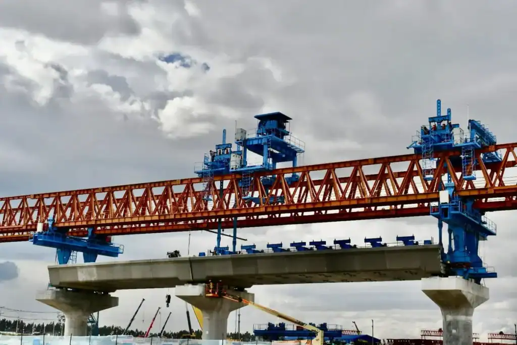
Safety devices are not decorations to cope with inspections. They are the final line of defense to guarantee the operation of hundreds of tons of heavy equipment. During selection, please pay close attention to these core safety guarantees:
- Build the core line of defense: Equipment must feature physical-level overload protection that forcibly cuts off the hoisting circuit. A gust alarm system for real-time monitoring of high-altitude working environments is necessary. Three-way limit protection to prevent operator errors is also mandatory.
- International standards and certification requirements: Do not get confused by fancy self-made certificates. Demand that manufacturers present internationally recognized safety certifications like ISO9001, CE, or OSHA directly. This is the stepping stone for equipment site entry. It also guarantees electrical and structural redundancy levels.
- Advance construction risk management: Do not wait for construction to begin before finding solutions. During procurement, require manufacturers to provide FMEA (Failure Mode and Effects Analysis) plans for extreme conditions. Clarify what physical interlocking and emergency lowering measures the equipment possesses if power fails or legs deviate during beam lowering.
Engineer’s Advice: Truly mature manufacturers will conduct construction sandbox simulations with you before delivery. Manufacturers who dare to provide FMEA plans show that their equipment safety logic withstands scrutiny.
Analyze Bridge Launching Gantry Costs from a Full Life-Cycle Perspective
| Cost Dimension | Main Content | Reference Proportion of Total Cost | Evaluation Focus | Impact on the Project |
| Initial Procurement Cost | Purchase fees for the main gantry, hoisting mechanism, electrical control system, and auxiliary equipment. | 30%-40% | Equipment performance, configuration level, and brand strength. | Determines the initial investment scale of the project. |
| Transport and Installation Cost | Equipment transportation, onsite assembly, commissioning, and inspection fees. | 10%-15% | Project location, transport conditions, and installation difficulty. | Affects project startup speed and budget. |
| Maintenance Cost | Daily inspections, lubrication, replacement of wearing parts, and periodic overhaul costs. | 15%-25% | Equipment reliability, parts commonality, and spare parts supply capability. | Affects equipment operation stability and long-term costs. |
| Energy Consumption Cost | Power consumption and operating costs of the drive system. | 10%-20% | Motor efficiency, frequency control technology, and energy-saving design. | Affects long-term operating expenses. |
| Downtime Loss Cost | Losses generated by troubleshooting, work stoppage waiting, and construction delays. | 15%-30% | Failure rate, after-sales response speed, and technical support capability. | Directly affects the schedule and project profits. |
| Personnel Training Cost | Operator training, safety training, and technical guidance fees. | 3%-5% | Manufacturer’s training system and technical document completeness. | Affects equipment utilization efficiency and construction safety. |
| Upgrade and Modification Cost | Automation upgrades, control system updates, and functional expansion fees. | 3%-8% | Modular design, compatibility, and expansion capability. | Affects future adaptability of the equipment. |
| Dismantling and Resale Cost | Dismantling, transportation, and second-hand resale fees after project completion. | 5%-10% | Brand value, equipment condition, and market demand. | Determines residual value and investment recovery rate. |
| After-Sales Service Cost | Technical support, remote diagnosis, and onsite service. | Hidden Cost | Service network coverage, response time, and technical strength. | Affects equipment availability and failure recovery speed. |
| Comprehensive ROI | Cost and benefit comparison throughout the full life cycle. | Comprehensive Indicator | TCO, equipment lifespan, and project utilization rate. | Determines final investment value. |
Case Analysis: Project with Increased Costs Due to Wrong Selection
In a cross-sea viaduct project in the Middle East, a contractor wanted to save 15% on initial procurement fees. They abandoned a customized solution from a professional manufacturer and bought a cheap, conventional double girder bridge launching gantry.
Consequently, they paid a painful price:
- Substandard anti-corrosion: Facing a high salt spray environment, the paint surface of the cheap model peeled off over a large area within three months. Electrical components short-circuited frequently. They had to spend heavily to hire a local team for a secondary anti-corrosion treatment.
- Expensive modifications: Because this model had poor micro-adjustment capability when passing holes, every pier-crossing required massive manual assistance for deviation correction. This severely dragged down progress. To catch up with the schedule, the contractor was forced to perform high-priced, temporary modifications on the trolley system onsite.
- Final accounting: Adding up delay penalties and extra maintenance costs, the money spent by this contractor on this equipment was 30% higher than the original price of a top-tier brand bridge launching gantry.
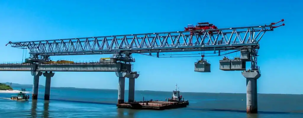
Choose an Experienced Bridge Launching Gantry Manufacturer
Selling equipment does not mean understanding construction. A reliable manufacturer provides equipment and ensures full-cycle protection across schemes, installation, and after-sales. When evaluating manufacturers, refer to the following table for a hard-core benchmarking:
| Key Evaluation Dimension | Benchmark Performance of Quality Manufacturers | Typical Pain Points of Substandard Manufacturers |
| R&D Strength | Provide 3D Finite Element Analysis (FEA) simulation reports and support digital pre-assembly. | Only provide generic drawings. Extreme onsite conditions require temporary cutting and modifications. |
| After-Sales Response | Permanent spare parts warehouses in core markets. Promise hour-level onsite troubleshooting. | Lack of spare parts and missing engineers. Long waiting times lead to high schedule penalties. |
| Onsite Guidance | Dispatch senior factory captains onsite to teach the construction team until independent operation. | Leave the instruction manual and walk away. Sudden gusts or deviations easily cause operator errors. |
| Contractual Promise | Write after-sales guarantees and downtime compensation clauses clearly into commercial contracts. | Avoid talking about responsibilities. Departments pass the buck to each other during quality disputes. |
Engineer’s Summary: Do not just look at the factory size. Look at whether the manufacturer’s engineers dare to visit the construction site. A manufacturer willing to put downtime compensation and onsite guidance into the contract is your most reliable shield.
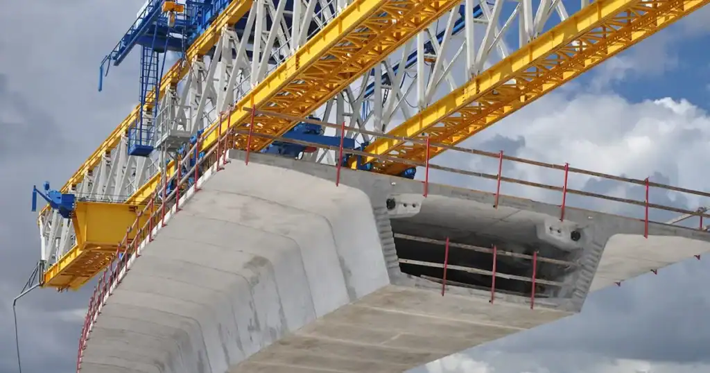
Forward-Looking Selection: Long-Term Considerations for Intelligent and Modular Expansion
Selecting a bridge launching gantry requires considering future project turnover, not just current bridges. Combining intelligence with extensibility is key to improving equipment asset Return on Investment (ROI).
- Reduce construction risks via intelligent control: Modern premium equipment should feature high-precision displacement sensors and integrated PLC control. This achieves millimeter-level synchronization across multiple mechanisms. The core feature is predictive maintenance. Real-time monitoring of vibration and temperature warns of failures before they happen. This avoids shutdown delays during critical node construction.
- Modular design: Project spans and working conditions of construction enterprises change frequently. A modularly designed bridge launching gantry, where main girders and legs use pin connections, adjusts components like building blocks. This lets the equipment switch flexibly between projects with different spans and working spaces, achieving multi-purpose utility.
- Reserved space for upgrades: Choose models where electrical cabinets and hydraulic pump stations reserve sufficient interfaces. This means future installations of LiDAR anti-collision or fully automatic hole-passing systems only require plug-in upgrades. It avoids expensive structural modifications and lowers asset depreciation costs.
Engineer’s Advice: Equipment that adapts to different sections via modular adjustment and features intelligent error-proofing guarantees construction efficiency. It also represents the core competitiveness for asset preservation and second-hand resale value.
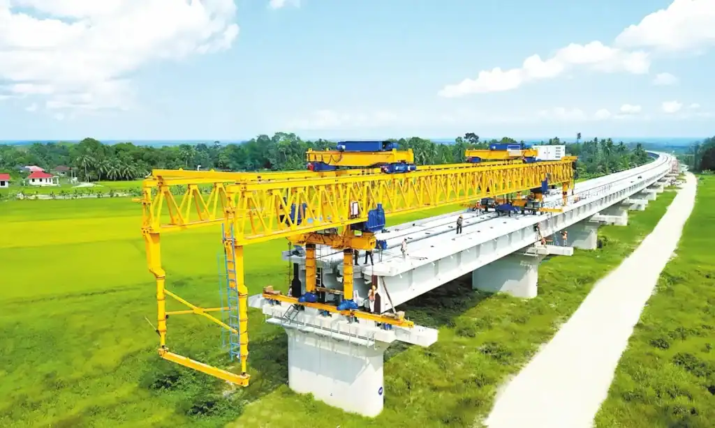
HSBRIDGE Bridge Launching Gantry Core Advantages
In the bridge launching gantry industry, reputation is built on hard-core projects. HSBRIDGE becomes the preferred brand for top construction enterprises by holding five core cards that address onsite pain points:
- High load capacity design: Core structures use special high-strength steel. High safety redundancy is reserved for extreme conditions like sudden gusts and biased loading. The main girder has high stiffness and low heavy-load deflection, giving onsite operators full security.
- Modular structural design: To solve entry difficulties in remote mountains, the entire series uses standardized pin connections. Conventional flatbed trailers handle delivery. Fast onsite assembly saves the project department huge fees for specialized transport and large crane rentals.
- Intelligent control system: Say goodbye to rough, purely manual blind operations. Standard configurations include full-frequency micro-movement systems and synchronous deviation correction technology. Beam lowering precision reaches millimeter levels. Combined with intelligent anti-sway algorithms, erecting tricky special-shaped bridges becomes easy.
- Global service network: We know downtime means burning money. Therefore, we establish localized spare parts warehouses in core markets. We promise 24/7 rapid response from factory engineers and full onsite training guidance. We never let the schedule delay while waiting for parts.
- Strict quality control system: Every process has an independent quality inspection code, from raw material cutting and full-penetration weld ultrasonic testing to factory pre-assembly under load. This fully complies with top international certifications like CE, withstanding the strictest safety inspections.
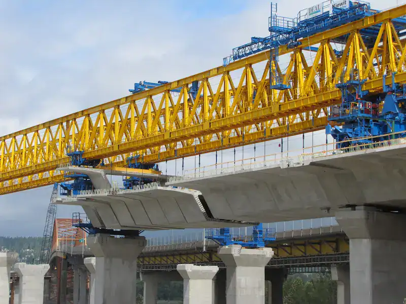
Conclusion
In large-scale bridge engineering, the error tolerance rate is always zero. We reviewed the 7 evaluation dimensions. They range from solid load parameters and terrain measurements to TCO analysis and technical heritage. They also include intelligent and expanded capabilities. This is not a superficial procurement process. It is a strict risk control system. Buying a bridge launching gantry seems like buying steel and control systems. Essentially, you buy project schedule certainty, absolute site safety, and project profit margins. Spend an extra week early on to simulate extreme conditions and calculate hidden costs. If it avoids one deadlocked downtime accident, this investment earns a hundredfold return.
Still no confident selection scheme? Hand it to professionals!
Every bridge project has its unique temper. Stop blindly copying generic sample brochures! If you have a tough project with large slopes, small curves, ocean corrosion, or harsh transport conditions, toss your design drawings and survey data to HSBRIDGE.
[Click here to contact the HSCRANE senior engineering team] We will provide a professional scheme within 24 hours. This includes 3D simulation previews, stress analysis reports, and customized selection quotes. Make every penny of your budget count where it matters most.
Do not let a wrong selection eat all your project profits
In bridge construction, saved procurement costs often return as multiplied losses during downtime repairs and rework. We summarized dozens of real engineering cases into this Bridge Launching Gantry Procurement Trap-Avoiding Guide. Read this piece to save millions in hidden costs.
[Click to view: 10 Questions to Ask Before Purchasing a Bridge Launching Gantry]
FAQ
Q: What is the most common mistake in equipment selection?
A: The typical error is focusing only on load capacity while ignoring site conditions. Many buyers blindly pursue large tonnages but find trailers cannot enter mountain roads. Ignoring logistics and foundation capacity is a fatal mistake causing budget overruns.
Q: How do you calculate the required lifting capacity accurately?
A: Multiply the total weight of the heaviest beam and rigging by a dynamic load coefficient. For coastal or canyon sites, you must also add wind load equivalents. Leaving a sufficient safety margin prevents emergency shutdowns during lifting.
Q: How do you choose between single and double girder gantries?
A: Choose single girders for short spans under 30 meters, sharp curves, or rapid relocation needs. Choose double girders for heavy-haul railways and cross-river bridges over 40 meters. Double girders offer superior wind resistance and hole-passing safety.
Q: What hidden factors affect price besides tonnage?
A: Prices vary based on non-standard customization, such as special hydraulic legs for steep slopes. Premium brands for core components like imported inverters also raise initial costs. Intelligent safety systems like anti-sway control add further value.
Q: How can you tell if a manufacturer is reliable at a glance?
A: Request a project-specific FEA report to verify their structural design capability. Next, check if they write troubleshooting response times directly into the commercial contract. Reliable manufacturers always back their equipment with strict contractual promises.
This document is for reference only. Specific operations must strictly comply with local laws and regulations and equipment manuals.

Get Expert Advice for Your Bridge Project
Our engineering team brings decades of experience in bridge construction equipment. Let us help you find the right solution.

 Scan to chat