

 Technical Insight
Technical Insight
Bridge Launching Gantry Capacity Calculation: From Girder Weight to Equipment Selection
Overview
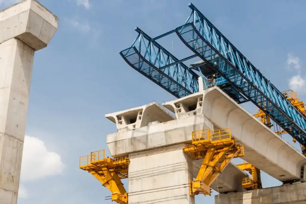
On bridge construction sites, the bridge launching gantry is the backbone of the project. Many contractors buy or lease equipment by checking design drawings. They often worry about one question. “The beam weighs 160 tons. What bridge launching gantry capacity should I choose?” Choosing capacity is not just matching the beam weight. A small capacity risks lives and engineering quality. An oversized capacity causes huge budget overruns and transport costs.
This article explains the capacity calculations clearly. We will discuss weight increases, site conditions, and dynamic load safety factors. We will also cover specific formulas and selection principles with real cases. Reading this prevents mistakes in choosing bridge launching gantry.
Are you planning a bridge project?
Stop worrying about complex parameters. Contact HSBRIDGE directly with your bridge types and spans. Send us your beam parameters. Our engineers offer free selection plans for your bridge launching gantry capacity. We help balance safety and costs.
What is bridge launching gantry capacity?
Simply put, the capacity on nameplates or manuals means rated lifting capacity.
It represents the maximum weight the equipment can lift safely in ideal conditions. The unit is tons. Think of it as the maximum physical limit of a bridge launching gantry. In actual construction, we never run the equipment at this extreme limit daily.
The difference between bridge launching gantry capacity and actual load weight
To understand better, we can break down bridge launching gantry capacity and key construction indicators:
| Key Indicator | Core Meaning | Construction Site Reality |
| Rated lifting capacity (bridge launching gantry capacity) | The maximum safe lifting ability designed for the equipment. | This is the ceiling. The actual lifting weight must never exceed this capacity. |
| Actual lifting weight | The beam weight plus rigging and spreader beams. | This is the real lifting load. Always include rigging weight when calculating bridge launching gantry capacity. |
| Dynamic load impact | Extra impact forces caused during lifting, braking, or traveling. | Braking or shaking creates forces larger than static weight. A higher capacity must handle this force. |
| Safety margin requirements | The buffer for uncontrollable factors like wind or uneven rails. | This is double insurance. You need a 20% margin for your bridge launching gantry capacity. |

Common bridge launching gantry capacity specifications
Different spans and beam types create various product lines. Mainstream bridge launching gantry capacity specifications form standard tiers:
| Bridge launching gantry capacity | Common Scenarios and Beam Matching |
| 80t | Used for small spans on rural roads and municipal bridges. It suits short hollow core slabs. |
| 100t | The main choice for municipal viaducts and provincial roads. It offers high mobility. |
| 160t | A common configuration for standard highway spans. It fits 30-meter T-beams or box girders. |
| 200t | Used for highways and heavy railways. It handles longer spans or wider girder bodies. |
| 320t | Designed for large highway interchanges and intercity railways. It suits heavy precast box girders. |
| 450t or higher | Exclusive for high-speed railway construction. Huge 450t to 900t bridge launching gantry capacity lifts full-span box girders. |
Understanding these concepts reveals a core logic. Always buy a larger capacity. How much larger should it be? Next, we enter the hard-core calculation for bridge launching gantry capacity.
Key Factors Affecting Bridge Launching Gantry Capacity Calculations
Calculating the bridge launching gantry capacity is like registering a weightlifter for a competition. You cannot just ask about the barbell weight and must check if they lift on flat ground or mud. You must also know if they lift once or a hundred times. Before showing formulas, we must list the hidden weights consuming the capacity.
Beam Dead Weight
The beam weight is the biggest load to carry. Different beam types on-site behave differently:
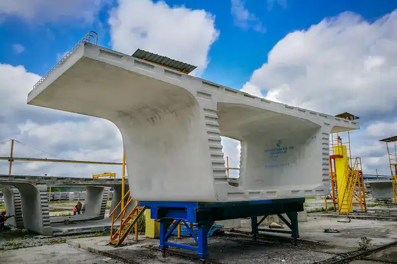
- Precast T-Beams and Concrete Box Girders: These solid giants have huge weight and concentrated centers of gravity. They present the most direct challenge to lifting mechanisms.
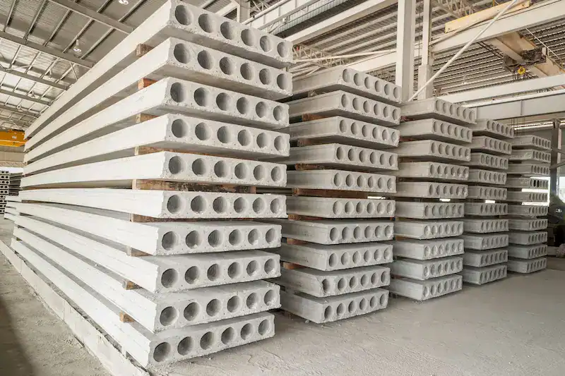
- Hollow Core Slabs: These lighter structures appear in small span projects. A small bridge launching gantry capacity handles them easily.
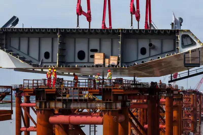
- Steel Box Girders: They weigh less than concrete beams but are often larger. A larger volume means a bigger wind area. This requires higher wind resistance and unbalanced load handling.
Experienced Engineer’s Advice: Never forget to include the weight of wire ropes, rigging, and spreader beams. These accessories often add up to several tons.
Beam Length and Span
Larger spans mean longer suspended parts of the bridge launching gantry. The bending moment on the main girder increases exponentially. Different spans determine the equipment size class:
- 20-Meter Beams: Low construction difficulty. Standard small and lightweight equipment handles them easily.
- 30-Meter Beams: The most common standard highway size. This is the main battlefield for the 160t to 200t class.
- 40-Meter Beams: A single beam weighs over 150 tons. This demands strict rigidity and traveling stability from the machine.
- 50-Meter and Higher Beams: For rivers, seas, or special elevated interchanges. This requires large customized equipment, often using dedicated guide-beam or self-balancing types.
Lifting Conditions
The construction plan directly affects equipment selection.
- Single-Machine Lifting: One machine handles lifting, traveling, and placing. The equipment must be an all-around performer with full indicators.
- Dual-Machine Lifting: Two machines handle extra-long or oddly shaped heavy beams together. The calculation gets complex. You must calculate load distribution during synchronization, not just total weight. The single machine capacity must exceed half the theoretical distribution weight.
- Continuous Erection: If the project has a tight schedule, equipment works continuously. To resist metal fatigue and heat from long operations, the capacity margin must be larger than normal.
Dynamic Load Impacts
Beginners often miss this factor. A static 100 tons is not 100 tons when moving.
- Startup and Braking Shocks: Winches lifting beams suddenly or braking during lowering create huge instant pulling forces.
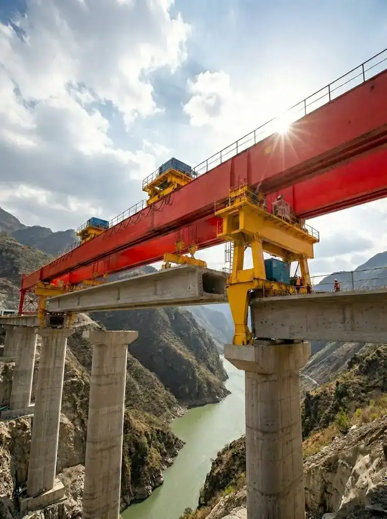
- Wind Loads: Working in canyon wind gaps or on high-pier bridges is challenging. Strong side winds push the machine and beam horizontally like an invisible force.
Rail Unevenness: Construction track conditions cannot be perfect like high-speed railways. A few millimeters of height difference causes unbalanced loads during movement. One leg might instantly bear pressure far
Safety Factor Requirements
In bridge engineering, safety is everything. After calculating all parameters, multiply by safety factors to leave a buffer. The industry uses these two factors:
- Dynamic Load Factor (1.1 to 1.3): Used to handle startup shocks and slight shaking.
- Safety Margin Factor (1.25 to 1.5): Used purely for risk prevention. If the environment is harsh with high winds or altitudes, use the 1.5 upper limit. Never risk safety to save equipment costs.
Detailed Explanation of Bridge Launching Gantry Capacity Formula
After laying all the groundwork, everything must come down to a specific number. Calculating the required bridge launching gantry capacity is not highly complex. Experienced site veterans hold a clear account in their minds.
Calculation Example for Bridge Launching Gantry Capacity
In actual selection and procurement, we usually apply the following industry-recognized safety baseline formula:
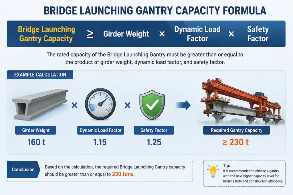
Bridge Launching Gantry Capacity≥Beam Weight×Dynamic Load Factor×Safety Factor
Friendly Reminder: The beam weight must include the weight of rigging, wire ropes, and accessories on the trolley.
Let us apply this formula directly to a common construction site scenario.
- Assumed Project Conditions: The drawings show a precast box girder weighing 160t. Based on site conditions, we set the dynamic load factor at 1.15 and the safety margin factor at a safe 1.25.
- Calculation Process: 160×1.15×1.25=230t. The theoretical requirement is 230t. However, equipment manufacturers usually do not have a standard model at exactly 230 tons.
- Selection Advice: The only principle here is to choose a higher option rather than a lower one. We strongly recommend selecting a 250t class machine. If your project has steep slopes, or if your company plans to handle heavier cross-river projects later, choosing a 300t class option offers better long-term cost-effectiveness and peace of mind.
Why Can You Not Choose Equipment Directly Based on Beam Weight?
Project owners often ask: “My beam weighs only 160 tons. Why force me to choose a 250-ton machine? Is this not wasting budget?” It is not. If you choose equipment at a 1:1 ratio based on beam weight, it becomes a ticking time bomb on site. The risks come from four main areas:
- Severe Startup and Braking Shock Loads: The winch lifting the beam creates a huge sudden pulling force. Sudden braking in mid-air also places immense stress on the wire ropes and metal main girders. This force is far larger than the static beam weight.
- Unavoidable Unbalanced Loads: Construction tracks cannot be as perfectly level as high-speed railway steel rails. Any small height difference or slight difference in winch speeds shifts the weight instantly to one leg. This creates dangerous unbalanced loads.
- Wind Loads as a Hidden Adder: Box girders have very large windward areas. Strong winds in open valleys or on high piers act like an invisible force pushing dozens of tons against the machine and beam horizontally.
- Structural Challenges of Long Spans: Larger spans increase the risk of main girder deflection or bending deformation during cantilever traveling. Ample capacity margins keep the metal structure rigid. This ensures the equipment remains stable when suspended over long spans.
Bridge Launching Gantry Capacity Options for Different Bridge Types
To help engineering professionals match options quickly during early planning, we have organized the standard configurations of mainstream projects into the table below:
| Bridge Engineering Type | Beam Characteristics and Environment | Common Bridge Launching Gantry Capacity Configurations | Selection Advice |
| Highway Bridges | Dominated by 30-meter and 40-meter precast T-beams or box girders. Spans are standard, often requiring long-distance continuous erection. | 160t, 200t, 250t | Highways are the main battlefield. Due to fierce competition and tight profit margins, we recommend choosing the highly versatile 200t class after meeting safety calculations. This facilitates equipment transfer and reuse later. |
| High-Speed Railway Bridges | Typical home of giants. Mostly full-span double-line box girders with massive weight, requiring extremely strict placement accuracy. | 450t, 600t, 900t | There is no room for compromise. These projects require large capacity box-girder machines with high rigidity, supported by highly automated control systems. |
| Municipal Bridges | Working space is usually limited. Projects are close to houses and pipelines, requiring high flexibility and easy disassembly. | 80t, 100t, 160t | Flexibility and mobility are top priorities. Municipal projects feature hollow slabs or small box girders. Do not chase massive capacity blindly. A small machine that gets the job done and transfers easily is preferred. |
| Steel Box Girder Bridges | Beam weight distribution is highly concentrated. The center of gravity is complex, and the wind resistance area is larger than traditional concrete beams. | Custom large capacity models recommended | Steel box girder lifting risks center-of-gravity instability and crosswind imbalance. Standard market equipment rarely fits perfectly. Manufacturers usually need to make non-standard customizations based on drawings, focusing on reinforcing the anti-unbalanced load capability of lifting mechanisms. |
Unsure How to Match Equipment with Your Drawing Parameters?
Do not gamble with expensive equipment procurement costs. If you are struggling with complex beam drawings, span parameters, and site terrain, leave it to our professional team.
Contact the HSBRIDGE Technical Center with your basic working conditions. We promise:
- One-on-one free accurate capacity calculations by senior engineers.
- Tailored equipment configuration plans that best fit your project budget and safety standards.
Let professionals handle professional tasks to eliminate trial-and-error costs in early equipment selection.
Other Crucial Parameters in Bridge Launching Gantry Selection
Accurately calculating the bridge launching gantry capacity completes only half the task. If equipment mismatches the site terrain or schedule, it will fail on-site. Align these five key parameters with technicians before procurement:
| Key Evaluation Parameter | Common Classifications | Practical Impact on Selection and Construction |
| Maximum Erection Span | 20m, 30m, 40m, 50m and above | Span determines main girder length and rigidity. 40 meters is a typical dividing line. Longer spans increase deflection risks during cantilever traveling, requiring customized structures. |
| Traveling Method | Step-by-step, guide-beam, self-balancing | This defines how equipment moves between piers. Step-by-step types offer high cost-effectiveness. Guide-beam types provide smooth traveling. Self-balancing types require no counterweights for high piers. |
| Bridge Curve Radius | Straight flat, small-radius curved | Many projects are not straight. When facing sharp curves, machines need strong transverse correction capabilities. Incorrect parameters prevent accurate beam placement and ruin engineering acceptance. |
| Longitudinal Slope | Plain flat, mountainous steep-slope | Mountain bridges feature high slope percentages. Working on steep slopes severely tests driving power and braking performance. Special configurations with larger climbing capabilities must be selected. |
| Project Schedule | Regular progress, urgent tight-schedule | Schedule means cost. If the client squeezes the timeframe, consider erection efficiency. Upgrading to variable frequency speed control or adding PLC automation helps accelerate progress. |
Product Advantages of HSBRIDGE Equipment
In the hardcore bridge equipment circle, buying machinery means buying peace of mind. HSBRIDGE is the top choice for leading contractors, relied on for solid product capabilities:
- Comprehensive Capacity Coverage: From flexible 80t municipal equipment to massive 900t high-speed railway options, our product line covers all ranges. You take the contracts, we match the equipment.
- Customized Design Capabilities: Even with oddly shaped steel box girders or steep mountainous viaducts, our technical team provides one-on-one tailored designs based on your construction drawings.
- High-Strength Structural Design: High-altitude operations leave zero room for trial and error. Our load-bearing structures comply strictly with FEM and ISO design standards. Critical welds undergo 100% Non-Destructive Testing (NDT) via ultrasound. Wind and deflection resistance far exceed industry baselines, delivering robust safety.
- Intelligent Control Systems: Moving away from outdated manual operation, our full line supports optional PLC intelligent systems. These include overload limiters, anti-unbalanced load alarms, and travel limit switches to minimize human errors.
- Global Project Service Experience: Our machinery has successfully served major infrastructure sites in dozens of countries across Southeast Asia and the Middle East. We provide full lifecycle technical support, from factory dispatch to overseas on-site installation and commissioning.
Engineering Case: How HSBRIDGE Helped a Client Select the Right Equipment
Real data speaks louder than theories. Last year, we handled a mountainous highway bridge project. Here is how the HSBRIDGE technical team helped the client avoid risks and finalize the procurement plan:
- Project Risks: The precast box girders featured a 40m span and a massive single weight of 180t. To cut procurement budgets, the client initially planned to use a 200t class machine to get by.
- Capacity Calculation Process: Considering mountainous gusts and high-altitude braking shocks, our engineers set the dynamic load factor at 1.15 and the long-span safety factor at 1.25. The actual equivalent load formula showed: 180\text{t} \times 1.15 \times 1.25 = 258.75\text{t}. We used this data to warn the client that using 200t equipment meant risking the entire project.
- Tailored Solution: After stopping the initial plan, we matched a 300t class machine for this section. The hardware featured a high-rigidity double main girder structure, resisting bending deformation risks during the 40-meter cantilever suspension. The control system integrated PLC intelligent control and automatic correction systems, solving beam placement challenges on curved sections.
- Project Outcomes: This equipment offered ample margins and a solid chassis. It achieved a 100% safety record with zero accidents throughout the construction period. Because the system ran smoothly, daily erection efficiency exceeded expectations. This helped the project department finish early, recovering the initial equipment budget.
How to Choose a Reliable Manufacturer?
Buying heavy machinery is not like purchasing standard supermarket parts. This expensive specialized equipment can become a massive burden if chosen incorrectly. Experienced engineers use these five criteria to screen out unreliable suppliers during evaluation:
| Core Evaluation Dimension | What Do Experienced Professionals Ask? | Risk Prevention Guide and the Harsh Reality |
| Professional Design Capability | “Do you have an independent technical team? Can you provide detailed stress calculation books and FEA reports?” | Manufacturers without core computing capabilities often use outdated drawings. They cannot optimize structures for complex conditions, creating massive safety hazards. |
| Real Project Experience | “Have you handled cases with similar spans? Do you have high-definition videos of actual on-site operations?” | Never let your key project become a testing ground. Building plain bridges differs from managing steep mountain slopes. Real combat experience refines machinery designs. |
| Customized Production Capability | “If my space is limited, or if I need extra wind resistance, can you modify drawings?” | Construction sites change constantly. If a manufacturer only pushes standard models, walk away. Powerful source factories always adapt equipment to fit your site. |
| On-Site Installation & Commissioning | “When equipment arrives on site, do you send a professional team to assemble and test it?” | Machinery delivery involves loose parts weighing hundreds of tons. Poor assembly guidance causes tolerance errors, uneven wear, or structural deformation later. |
| After-Sales Support System | “If electrical components fail, how fast do parts arrive? Are engineers available online during late-night faults?” | Bridge construction involves strict tight deadlines. Equipment breaking down creates massive daily financial losses. Rapid-response support serves as vital insurance for your project timeline. |
Conclusion
In conclusion, calculating the bridge launching gantry capacity is never just simple multiplication with a calculator. It is a systematic process requiring comprehensive planning. You must evaluate complex site conditions, dynamic load shocks, spans, and even unpredictable wind conditions.
A scientific and rigorous selection plan takes responsibility for frontline workers’ lives. It acts as an anchor to improve erection efficiency and avoid huge cost overruns from downtime. For experienced construction enterprises, choosing a knowledgeable, reliable manufacturer saves most troubles during project execution.
Ready to Pick the Best Assistant for Your Project?
Whether you need standard equipment or special models for complex terrain, choosing correctly is never a small matter. Contact HSBRIDGE directly and share your drawings to instantly get:
- ✓ One-on-one free accurate capacity calculation services.
- ✓ A free tailored selection plan for your project.
- ✓ Customized design support for complex bridge types and extreme conditions.
- ✓ Global transportation and installation guidance from factory to site.
Equipment Selection Guide
Beam weight does not equal the rated capacity. In bridge construction, always buy one size larger. But how do you calculate this extra margin scientifically? From formula derivation to actual condition analysis, one article helps you safeguard equipment procurement safety and cost.Recommended Reading:Launching Girder Capacity Calculation: How Beam Weight Determines Your Equipment Choice
FAQ
Q: The drawing shows a 100t precast box girder. To save budget, can I customize a 100t machine?
A: Absolutely not. Rated capacity is a maximum safety limit. Total forces easily exceed 100t due to rigging and shocks. A 100t beam requires a 120t or 160t machine.
Q: Is there a necessary connection between the bridge launching gantry capacity and span?
A: Yes, directly. Larger spans increase bending risks during cantilever traveling. For long spans, you must upgrade to higher rigidity and capacity to ensure safety.
Q: We are building a mountain highway with a 4% slope. What requires special attention during selection?
A: Steep slopes severely test driving and braking systems. Standard configurations risk slipping. You must ensure baseline capacity and upgrade lifting brakes and anti-slip devices.
Q: Why do quotes for identical “200t machines” from different manufacturers differ by thousands of dollars?
A: Differences lie in unseen details like steel thickness and component brands. Cheaper equipment cuts advanced PLC safety systems and installation guidance. This leads to expensive downtime.
This document is for reference only. Specific operations must strictly comply with local laws and regulations and equipment manuals.

Get Expert Advice for Your Bridge Project
Our engineering team brings decades of experience in bridge construction equipment. Let us help you find the right solution.


 Scan to chat