 EN_US
EN_US  Español
  Русский
  العربية
  Português do Brasil
  Français
  Bahasa Indonesia
  Türkçe
  Tiếng Việt
  Bahasa Melayu
  Українська

 Technical Insight
Technical Insight
How Bridge Launching Gantry Traveling Speed & Stability Shortens Project Timelines
Overview
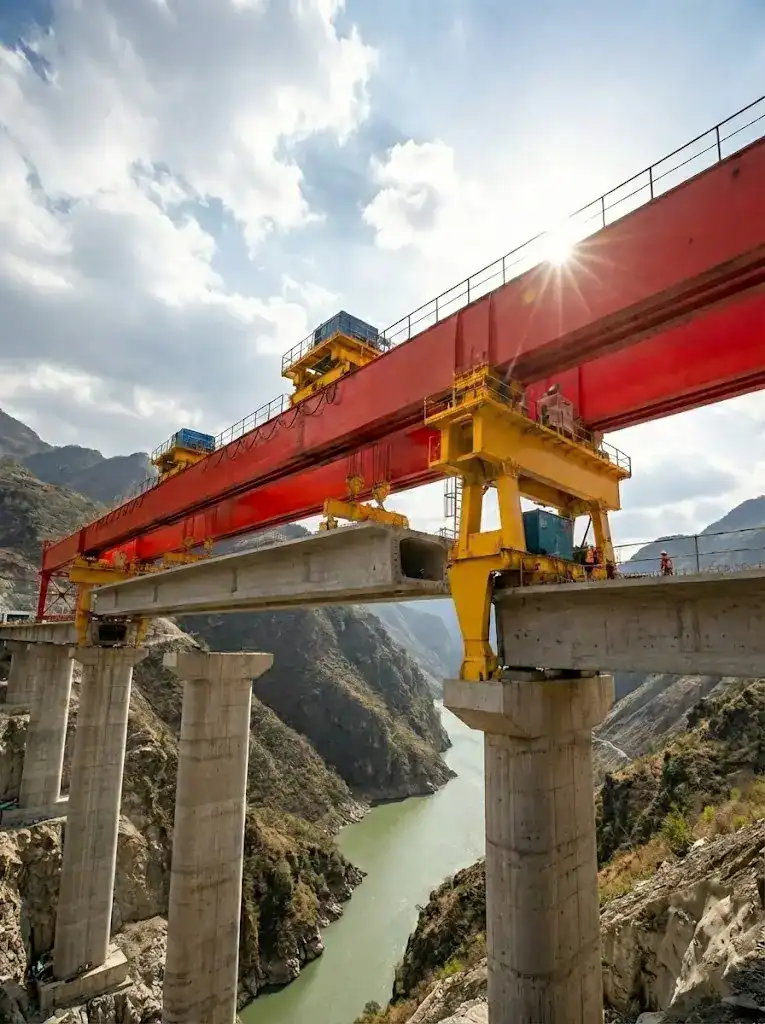
Every day your bridge girder erection gantry runs below its true traveling speed potential, you lose more than just time. On a typical 8-span viaduct, a 15% slower-than-planned traverse speed can add 3–4 weeks to the critical path—costing over $200,000 in additional site overheads. For a procurement manager, understanding and specifying the right bridge launching gantry traveling speed isn’t an academic exercise; it’s the difference between hitting a completion bonus and watching the liquidated damages clock tick.
This article translates the physics of gantry travel into dollars, hours, and actionable specification requirements, so you can evaluate proposals not just by horsepower promises, but by cycle-time evidence.
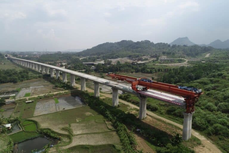
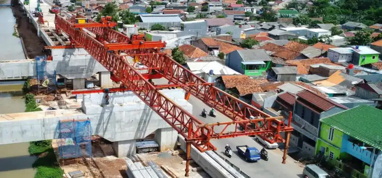
In bridge engineering, bearing installation and girder positioning define the critical path. As the core equipment for precast girder construction, bridge launching gantry traveling speed directly impacts cycle times. It also dictates inter-span transition efficiency. In high-turnover environments, optimizing traveling performance via frequency conversion is essential. This compresses total project duration within safety limits and improves resource synergy.
Defining Bridge Launching Gantry Traveling Speed
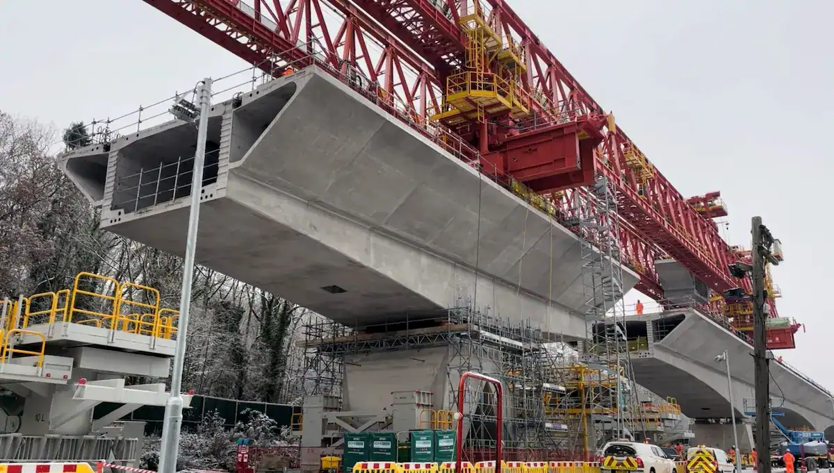
Bridge launching gantry traveling speed is the velocity at which the gantry’s main frame and trolley assemblies move, measured in meters per minute (m/min) under defined load conditions. It is the primary variable that determines how many beams you can place per day—and whether your sequence stays ahead of the weather window.
Speed is never a single number. The gantry operates in four distinct motion modes, and the smart specification differentiates each one.
Longitudinal vs. Transverse: A Comparison Table
Motion Type | Typical Speed Range (Loaded) | Typical Speed Range (Empty) | Role in Cycle Time | Key Constraint |
Longitudinal travel (gantry along bridge axis) | 1.5 – 6.0 m/min | 6.0 – 12.0 m/min | Moves gantry between spans; positions feeding zone | Track grade, wind load, self-weight inertia |
Transverse trolley travel (cross-beam positioning) | 1.0 – 3.5 m/min | 3.0 – 8.0 m/min | Fine alignment of girder over bearings | Beam sway, micro-positioning accuracy |
Hoisting speed (vertical) | 0.3 – 1.2 m/min | 1.0 – 4.0 m/min | Lifting girder from feeder to placement height | Load stability, brake response |
Self-propelled crossspan travel (empty gantry advance) | N/A | 5.0 – 10.0 m/min | Repositioning to next span (nonproductive time) | Guiderail alignment, wind gust limit |
Note: Loaded speed limits are often set by the permissible dynamic factor ψ and the calculated deflection under acceleration.
In practice, transverse trolley speed has an outsized influence on effective cycle time per beam. Unlike longitudinal travel—which you may execute only once per span—girder positioning requires multiple transverse passes and micro-adjustments. Improving trolley speed from 2.0 m/min to 3.0 m/min while maintaining ±5 mm positioning accuracy saves 8–12 minutes per beam, or roughly one extra beam every two shifts.
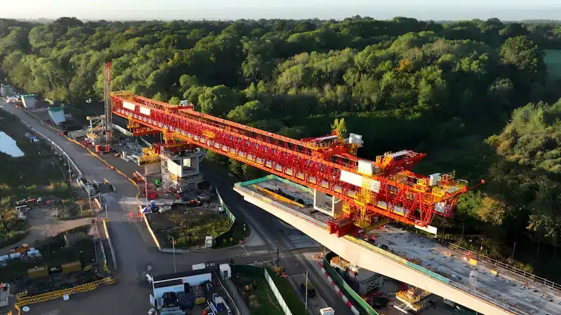
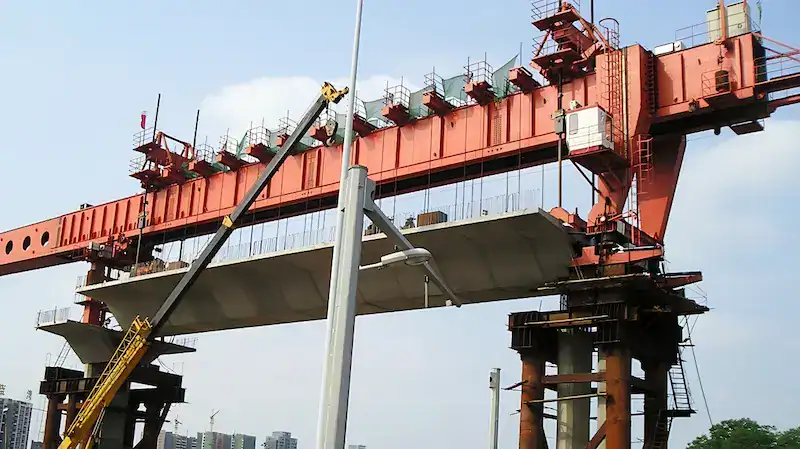
Velocity Differences Under No-Load and Loaded Conditions
The equipment typically operates under two speed standards based on the load status:
- Loaded Speed:The speed while lifting or carrying precast girders. It is limited by load inertia and structural stability. This speed focuses on smooth starting and precise braking.
- No-Load Speed:The speed during trolley return or full machine transitions. Increasing this frequency reduces non-productive time. It is a key factor in optimizing the construction cycle.
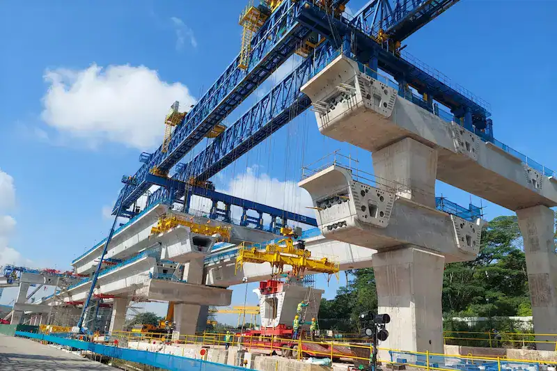
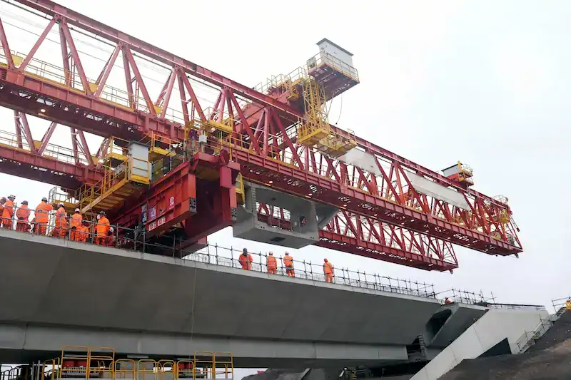
How Traveling Speed Impacts the Construction Cycle
Impact on Single-Span Erection Time
Precast girder erection follows a standard cycle of transport, feeding, lifting, and lowering.
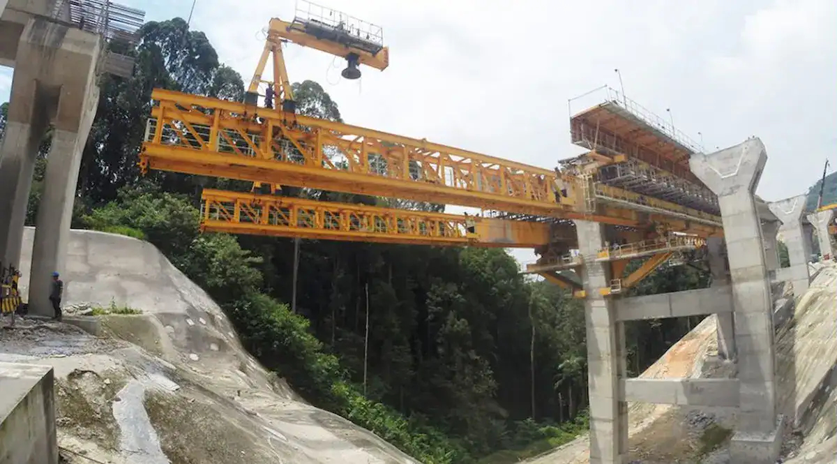
- Linear Efficiency Correlation:Physical movement consumes 30% to 40% of the erection time per girder. Faster longitudinal feeding and transverse positioning directly shorten each cycle.
- Daily Output Increase:Assume a span requires six girders. Increasing bridge launching gantry traveling speed by 20% gains 0.5 to 1.0 hour daily. This allows for more completed girders across multiple shifts.
Determining Equipment Transition Efficiency
Transitioning between spans after completing an erection is a non-productive downtime phase.
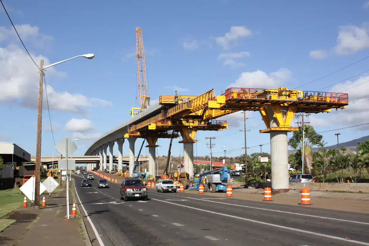
- Reducing Transition Time:The self-launching speed of the machine determines how soon the next span begins.
- Cumulative Effect:On long bridges, saving time during each transition creates a massive cumulative advantage. This provides a significant schedule buffer in the project’s later stages.
Optimizing Resource Coordination Efficiency
The gantry acts as the central hub for all onsite production elements.
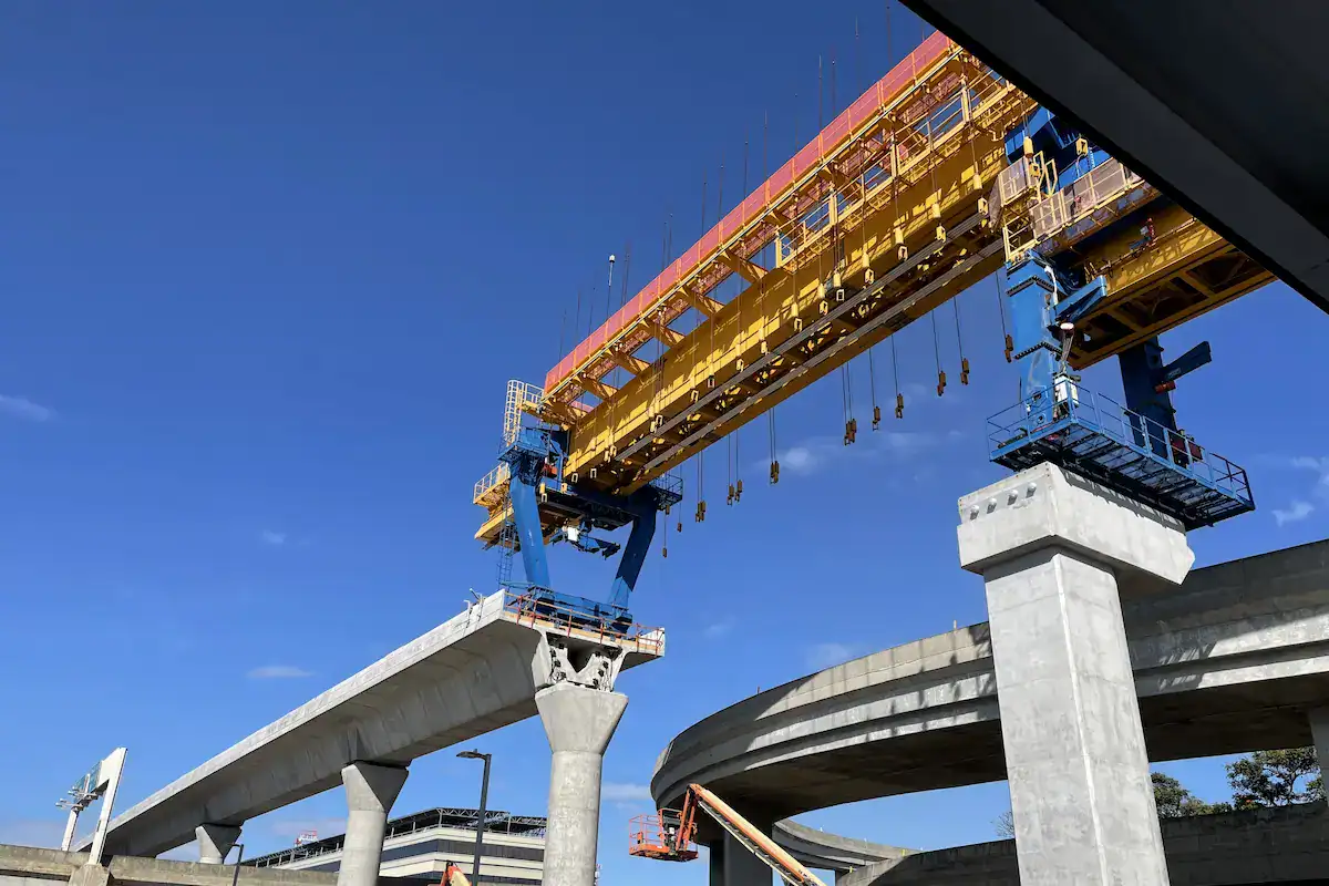
- Eliminating Bottlenecks:Slow bridge launching gantry traveling speed causes “passive waiting” for transport vehicles and onsite crews.
- Lowering Rental Costs:Reducing idle time shortens the rental duration for supporting equipment. This optimizes the overall mechanical cost per shift.
Impact on Total Project Duration
Schedule control relies on optimizing the critical path.
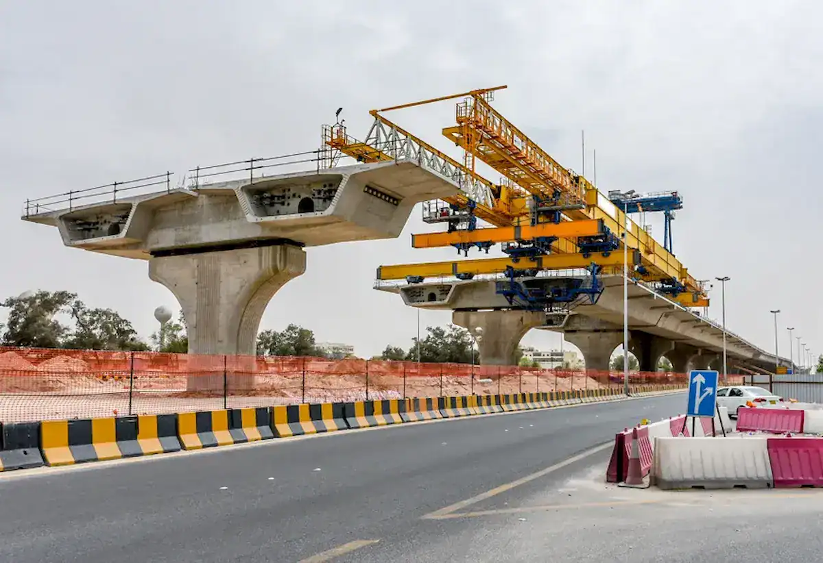
- Cycle Comparison Analysis:Under identical conditions, high-performance systems can shorten total bridge construction by 10% to 15%.
- Precision and Speed:Precise frequency control allows high speeds for long distances. It also enables low speeds for accurate positioning, preventing time wasted on repeated adjustments.
Key Factors Influencing Bridge Launching Gantry Traveling Speed
The bridge launching gantry traveling speed is not a fixed value. It is a complex variable determined by structure, power systems, and working conditions.
Critical Factors and Impact Logic
Key Factors | Core Impact Point | Speed Influence Logic | Optimization Direction |
Structural Design | Rigidity and Torsion | Double girders offer better stability than single girders. Stable frames absorb shocks and allow higher lateral speeds. | Strengthen main girder rigidity to provide a physical basis for speed increases. |
Drive System | Frequency Control | Inverters determine speed smoothness. Sufficient power prevents “creeping” under load and ensures precise braking at high speeds. | Use high-power motors with advanced frequency systems for stepless speed control. |
Environment | Slopes and Wind | Steep slopes increase motor load. Strong winds create lateral forces. Poor rail leveling causes vibration, forcing speed limits. | Monitor environmental data in real-time. Adjust safe speed limits based on slope and wind. |
Girder Traits | Weight and Span | Heavier girders increase rotational inertia. Large spans require strict speed limits to reduce dynamic deflection and inertial impact. | Set specific operation curves for heavy or long-span girders to balance safety and efficiency. |
Technical Specs | Precision and Rules | Bearing installation requires millimeter precision. This forces “micro-speed” modes. National safety standards also set maximum speed limits. | Use intelligent positioning systems to reduce the time spent in low-speed fine-tuning modes. |
Technical Advancement: In practical engineering, speed settings must strictly follow the load curve. No-load traveling speeds are typically set higher to save time. Conversely, loaded transverse movement must use precision speed modes. This ensures sufficient safety redundancy for the equipment structure.

Is Faster Always Better for Bridge Launching Gantry Traveling Speed?
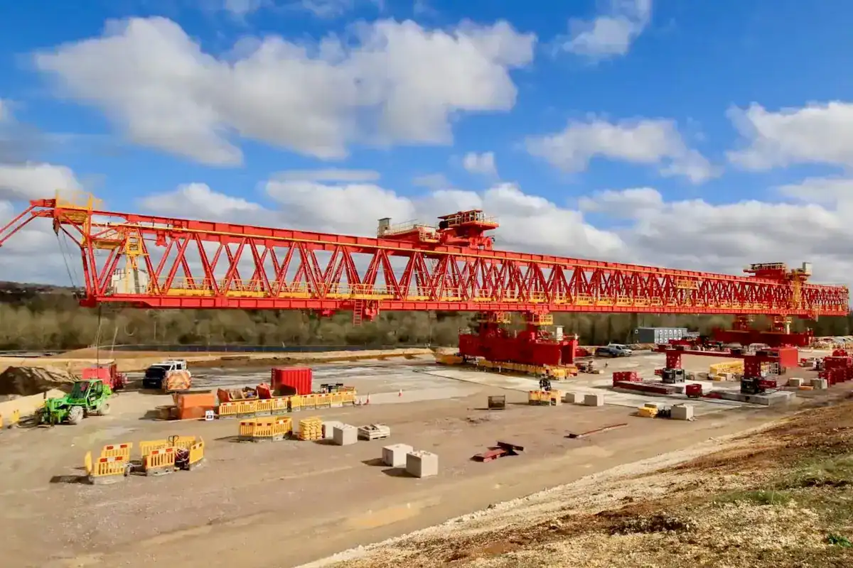
In practice, pursuing high mechanical speed does not always equal high construction efficiency. Operation must follow the constraints of dynamic stability and engineering precision.
High Speed Does Not Equal High Efficiency
Efficiency depends on effective cycle time rather than just displacement speed.
- Diminishing Returns:Exceeding structural stability thresholds increases adjustment time during braking and positioning. This may actually increase the total time per girder.
- System Synergy Limits:If speed exceeds the supply capacity of transport vehicles, the gantry remains idle. This fails to convert speed into actual productivity.
Risks of Blindly Increasing Speed
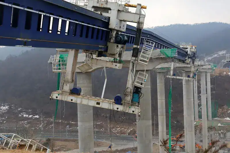
- Increased Positioning Errors:Higher speeds make inertial braking harder to control. Girder swaying makes millimeter-level positioning difficult, requiring frequent and time-consuming corrections.
- Accelerated Equipment Wear:Frequent high-speed starts and stops increase stress on reducers, gears, and wheels. This shortens component life and increases unplanned maintenance downtime.
- Elevated Safety Risks:Higher speeds increase dynamic load coefficients. In windy or sloped conditions, blind speeding can lead to overturning, derailment, or structural fatigue.


Balancing Safety and Efficiency
The optimal solution is “Full-Process Speed Management”:
- Strategic Speed Regulation:Use high speed limits for long-distance no-load travel. Switch to micro-speed modes during heavy-load positioning for smooth transitions.
- Rigidity Support:Higher speeds require sufficient vibration damping capacity. Strengthening main girder rigidity helps offset vibrations caused by high-speed movement.
- Intelligent Redundancy Control:Use sensors to monitor status in real-time. The system should automatically reduce speed if wind or slope exceeds safe values.
How to Optimize Bridge Launching Gantry Traveling Speed to Shorten Construction Cycles
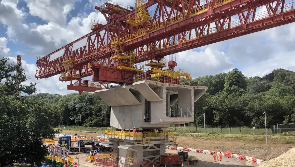
Optimizing bridge launching gantry traveling speed is not about simply increasing motor RPM. It requires integrating equipment design, control systems, and site coordination to maximize efficiency rather than just raw speed.
Dimensions for Optimization
Optimization Dimension | Key Technical/Management Measures | Impact on Construction Cycle |
Parameter Matching | Selection Optimization: Customize gear ratios and motor efficiency based on bridge type (T-beam/Box) and span. | Ensures rated speed limits under full load. Eliminates “creeping” delays caused by insufficient power or rigidity. |
Intelligent Controls | VFD & Auto-Sync: Use PLC-integrated Variable Frequency Drives for soft starts. Apply auto-sync technology for trolley movement. | Enables millimeter-level precision. This reduces alignment time by over 20% by eliminating repetitive manual adjustments. |
Site Organization | Integrated Coordination: Use wireless systems to link beam carriers and gantries. Optimize the sequence between feeding and erecting. | Eliminates “time gaps” between processes. Keeps equipment in a continuous high-efficiency cycle by tightening the critical path. |
Preventive Maintenance | Health Monitoring: Regularly check wheel wear, oil quality, and rail leveling. Perform scheduled maintenance on drive systems. | Prevents unplanned downtime. Avoiding a single mechanical failure can save days or even weeks of schedule delays. |
Technical Insight: In practical engineering, 20% of the movement is heavy-load traveling, which dictates construction safety. However, the remaining 80%—consisting of no-load returns and inter-span transitions—is the primary area for shortening the project duration. Using intelligent systems to safely increase no-load displacement speed is the industry’s recognized path for optimization.
Why Choose HSCRANE Bridge Launching Gantries?
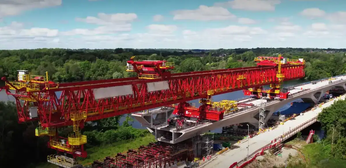
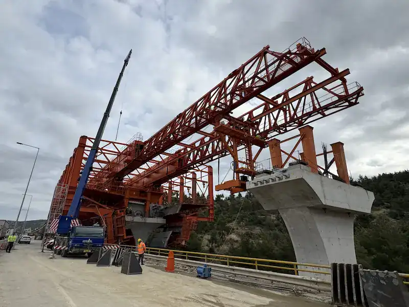
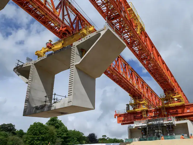
In complex bridge construction management, HSCRANE bridge launching gantry is the top choice for global contractors. We optimize schedules through superior power performance and structural reliability.
Core Advantages of HSCRANE
- Customization for All Conditions:We cover highway T-beams, railway box girders, and urban viaducts. Our designs follow ISO, FEM, and GB With capacities from 40t to over 900t, we ensure parameters match project needs perfectly.
- High-Efficiency Drive Systems:We optimize gear ratios and frequency drive algorithms. This significantly boosts displacement speeds in both loaded and no-load states. By cutting non-productive time, we directly shorten the single-span erection cycle.
- High-Stability Steel Structures:Using high-strength steel (like Q355B/Q355D) and optimized sections, our machines offer extreme wind and torsion resistance. They maintain smooth operation even in mountains, on high piers, or during long-distance projects.
- Intelligent Integrated Control:Advanced PLC units support multi-point auto-sync and millimeter-level positioning. Our intelligent anti-sway system reduces operational difficulty and enhances safety during high-frequency cycles.
- Global Project Experience:HSCRANE equipment is used on high-speed rail lines and major infrastructure worldwide. We offer proven solutions for curved bridges, skewed bridges, and other extreme conditions.
- Life-Cycle Support:We provide end-to-end technical assurance. This includes site surveys, custom design, installation, training, and global spare parts supply to maximize equipment uptime.
Looking for High-Efficiency Solutions?
If you want to speed up project delivery and lower operational risks, contact the HSCRANE expert team today. We provide professional custom proposals and real-time quotes.
[Contact Us for a Custom Solution]
Conclusion
The bridge launching gantry traveling speed is a vital performance metric and a core variable in schedule management. Based on our analysis of speed, transition efficiency, and resource synergy, we conclude:
- Speed is the Foundation of Efficiency:Optimizing movement directly reduces cycle times. On large-scale projects, this cumulative effect significantly shortens the total delivery period.
- Safety is the Boundary for Speed:Blindly seeking high speeds risks dynamic impact, errors, and wear. Efficient erection requires a balance between structural rigidity and dynamic stability.
- Smart Selection Controls the Schedule:The best path to a shorter cycle is not just faster motors. It requires matching equipment parameters, applying sync technology, and optimizing site organization.
Choosing bridge launching gantries with high-precision control and stable structures is the best engineering guarantee for safe, high-speed delivery.
Further Reading: From Speed Theory to On-Site Operation
How do you transform speed parameters into standardized site workflows?
[Click to Learn More] Bridge Girder Launcher Construction Process: Erection & Span Passing
Key Values:
- Process Breakdown:A deep dive into full-cycle operations from the first abutment to the final span.
- Coordination Points:Clear operational standards for traveling mechanisms during beam feeding and lowering.
- Risk Control:Detailed safety checklists for key nodes to ensure high efficiency and safety.
FAQ
Common engineering questions regarding bridge launching gantry traveling speed and efficiency:
Q: Does higher speed significantly increase power consumption?
A: Higher speeds require more power, but Variable Frequency Drives (VFD) optimize output based on load. Shorter cycle times often balance total energy use per unit.
Q: How are safe speeds set for steep mountain slopes?
A: On slopes above 3%, loaded speed should be reduced below 50% of the rated limit. Use dual mechanical and electromagnetic braking to prevent sliding.
Q: How does maintenance frequency affect the schedule?
A: Traveling parts wear quickly. Neglecting lubrication or rail checks increases friction and downtime. Preventive maintenance avoids long-term labor idling from mechanical failure.
Q: Why is speed limited even with sufficient motor power?
A: Limits are often due to structural resonance. If movement frequency matches the girder’s natural frequency, severe vibration occurs. Wire rope sway also acts as a physical constraint.
This document is for reference only. Specific operations must strictly comply with local laws and regulations and equipment manuals.

Get Expert Advice for Your Bridge Project
Our engineering team brings decades of experience in bridge construction equipment. Let us help you find the right solution.

 Scan to chat