 EN_US
EN_US  Español
  Русский
  العربية
  Português do Brasil
  Français
  Bahasa Indonesia
  Türkçe
  Tiếng Việt
  Bahasa Melayu
  Українська

 Technical Insight
Technical Insight
Launching Girder Capacity Calculation: How Beam Weight Determines Your Equipment Choice
Overview
Selecting the correct launching girder capacity is directly related to essential construction safety. The core selection logic follows: rated equipment tonnage ge total beam weight times safety factor (1.1-1.4). Impact from dynamic loads, wind loads, and braking inertia on girder deflection and outrigger stability must be strictly calculated. For 30m T-beams, 40m box beams, and high-speed rail 900t box beams, equipment must match the load grade. Overload operation is strictly prohibited to avoid structural fatigue and collapse risks.
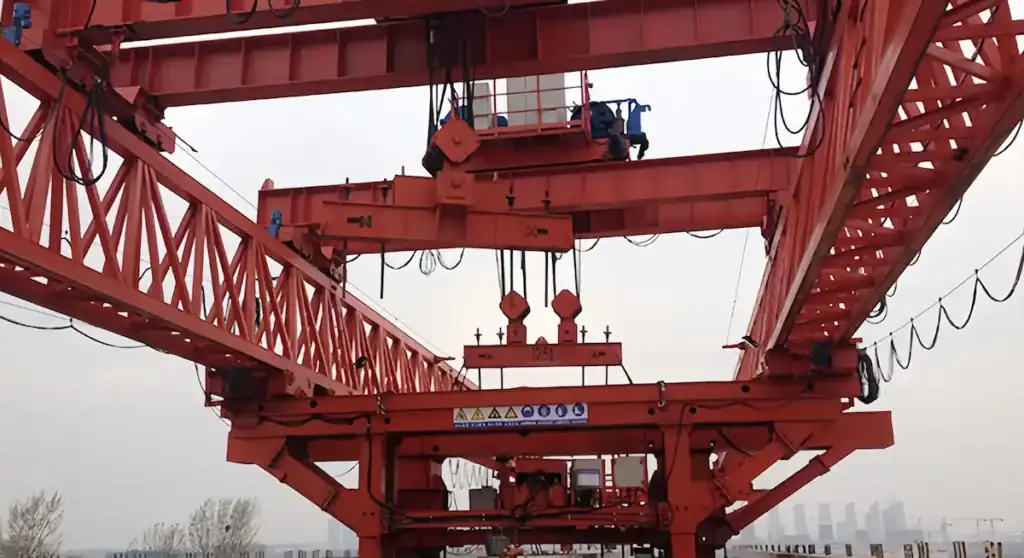
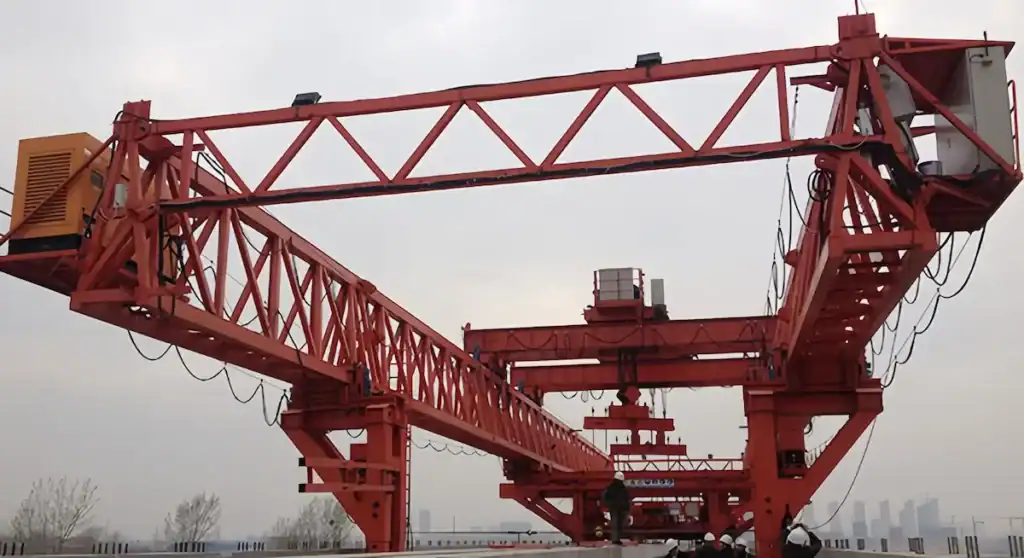
HSCRANE launching girders cover requirements from 80t to 900t for all working conditions. They feature high-rigidity structural design and automated lifting control. The equipment shows high positioning accuracy and anti-overturning stability on skewed bridges, curved bridges, and extreme terrain. Following successful large-tonnage projects in Indonesia and elsewhere, HSCRANE provides customized technical support globally. We ensure safety margins while significantly improving bridge erection efficiency and equipment turnover.
Why Beam Weight Drives Capacity Selection
The Launching Girder’s Role in Bridge Construction
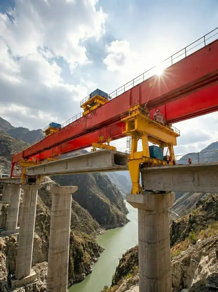
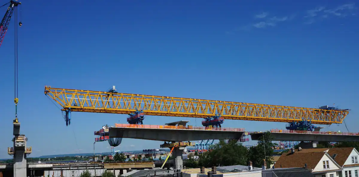
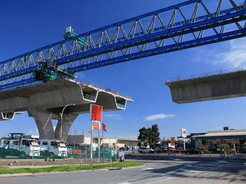
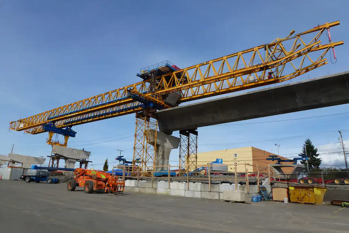
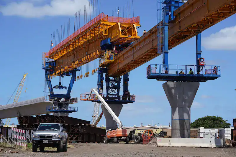
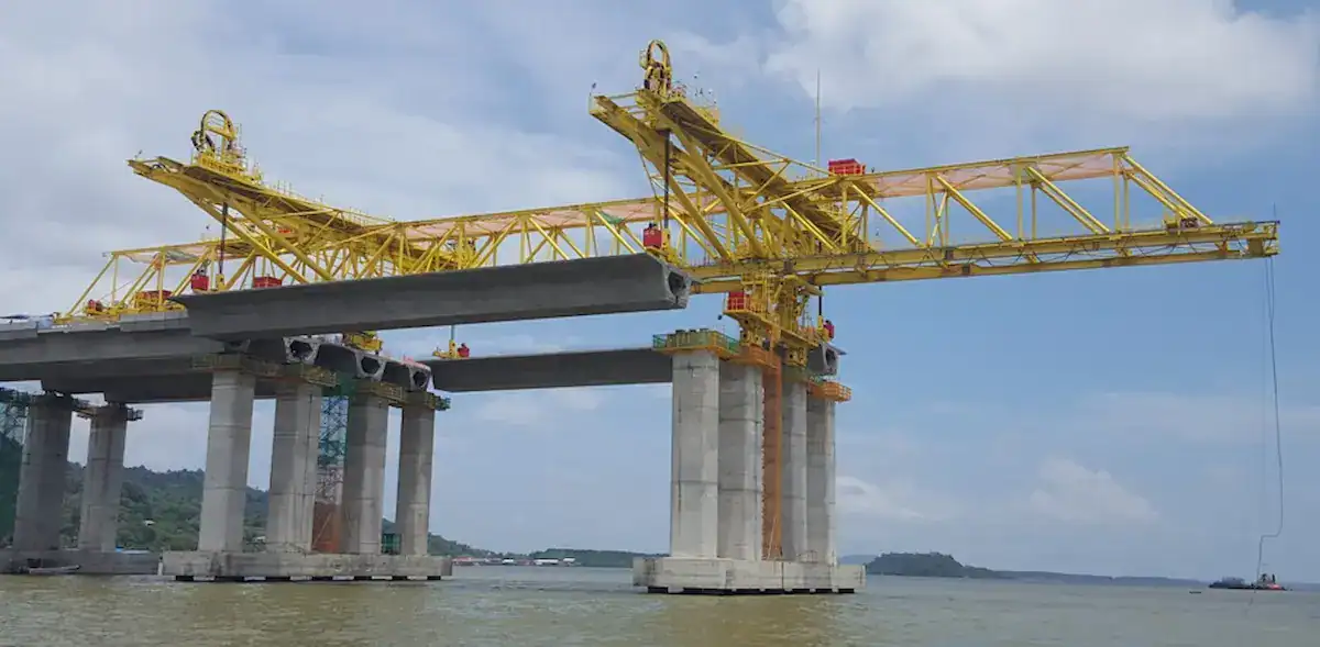
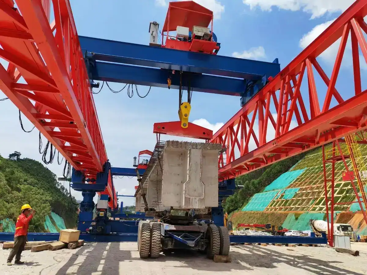
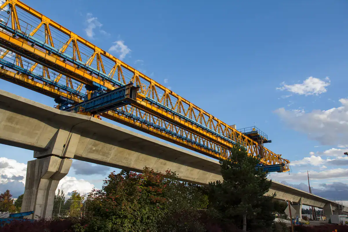
A bridge launching girder is the primary load-bearing machine in precast segmental bridge construction. It lifts each precast beam from the transporter, travels longitudinally along the bridge axis, and lowers the beam into its final position — typically within ±5 mm of the design coordinates.
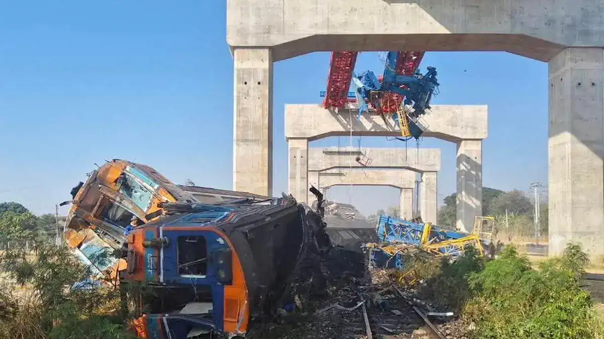
The machine’s main girder, hoisting mechanism, and support legs form a closed structural system. When the beam weight exceeds the girder’s design bending moment capacity, you get more than performance degradation — you get plastic deformation of the main girder, weld cracking at high-stress nodes, or hydraulic leg instability. These are not theoretical failure modes; they are documented causes of bridge construction accidents.
Key engineering checks at the selection stage:
- The girder’s rated capacity must exceed the heaviest beam segment by a minimum factor of 1.10
- Main girder mid-span deflection under full load must stay below L/800(per GB/T 3811 and FEM 1.001)
- Support leg reaction forces must be calculated for the worst-case load position at every span
Direct Impact of Beam Weight on Equipment Safety
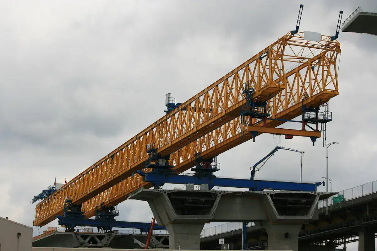
Beam weight is the base data for calculating lifting torque, outrigger reaction, and structural fatigue. If load distribution exceeds design thresholds, the main girder will experience excessive instantaneous deflection. This leads to cracked welds or unstable hydraulic outriggers. Ensuring the launching girder capacity slightly exceeds the beam weight provides necessary safety redundancy for dynamic impacts or uneven settlement.
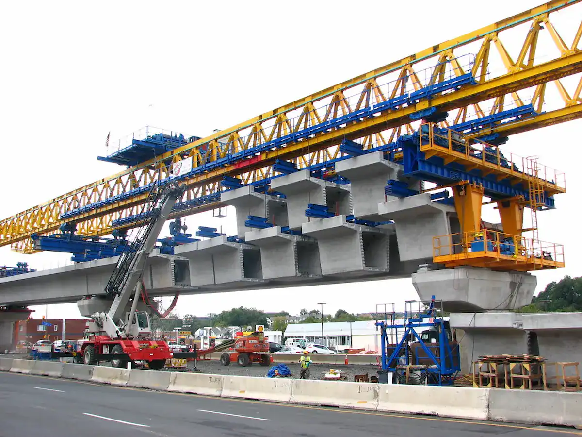
Under-Sizing vs. Over-Sizing: Neither Is Free
Scenario | Consequences |
Capacity too low | Hoist motor burnout, wire rope failure, main girder plastic deformation, tipping risk. Structural fatigue accelerates — micro-cracks propagate at welds, reducing service life by 40%–60%. |
Capacity too high | Excessive self-weight increases bridge deck loading and transport costs. Motors operate at low utilization, wasting power. Capital cost increases by 15%–25% with no safety benefit beyond a reasonable margin. |
The goal is right-sizing — matching capacity to beam weight with an engineered safety margin, not guessing conservatively and paying for unused steel.
Capacity Requirements by Bridge Type
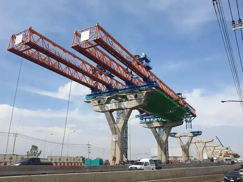
Different bridge categories demand distinct lifting capacity ranges:
- Highway bridges (20m–40m spans): T-beams and small box beams dominate. Typical launching girder capacity range: 100t–200t.
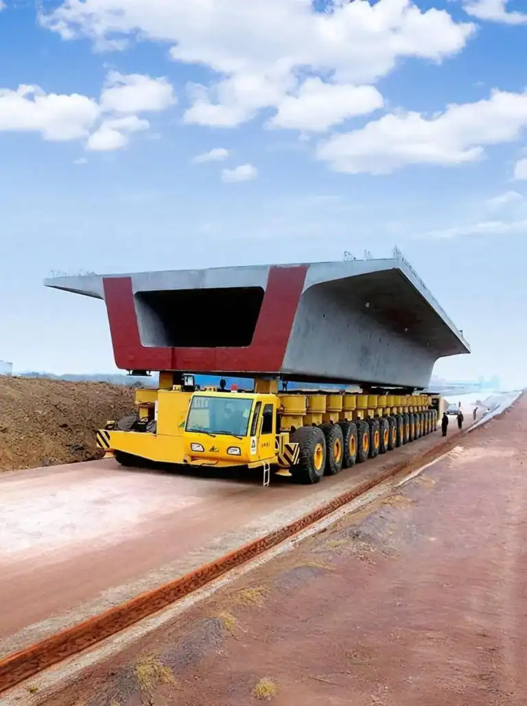
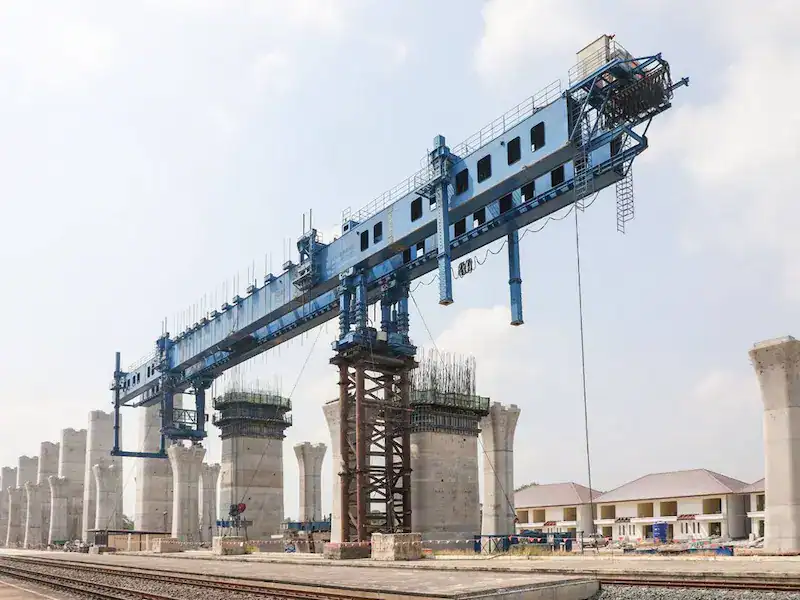
- High-speed railway (32m full-span box beams): Standardized 900t-class precast segments require purpose-built launching gantries rated at 900t and above, often integrated with the transporter as a single unit.
- Urban metro / light rail: Segmental precast erection with spans under 30m. Capacity typically below 100t, but positioning accuracy requirements are stricter due to tight clearance envelopes.
Understanding Launching Girder Capacity Ratings
Rated Capacity Defined
Rated capacity (Gn) is the maximum safe working load a launching girder is designed to lift under specified operating conditions. It is the governing parameter for structural design, stability verification, and hoist mechanism selection. Every lifting device on the machine — hoist, trolley, spreader beam — must be individually rated to this value.
Two distinct load states must be understood:
Load State | Definition | Design Consideration |
Static Load (G) | The actual physical weight of the precast beam at rest | Determines the main girder’s ultimate bending moment capacity. This is the baseline for all calculations. |
Dynamic Load | Additional forces from lifting acceleration, braking deceleration, and machine vibration | Covered by a dynamic coefficient (φ = 1.10–1.25) applied to the static load. This ensures the structure remains within its elastic range during hoisting transients. |
For a 200t beam, the effective design load is not 200t — it is 200 × 1.25 = 250t. The dynamic coefficient is multiplicative, not additive.
Capacity Ranges by Project Scale
Capacity Class | Typical Range | Application |
Light | 80t–120t | County roads, rural bridges, 20m-class T-beams, hollow-core slabs |
Medium (Industry Standard) | 160t–300t | National highways, expressways, 30m–40m T-beams and box beams |
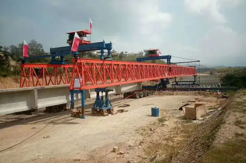
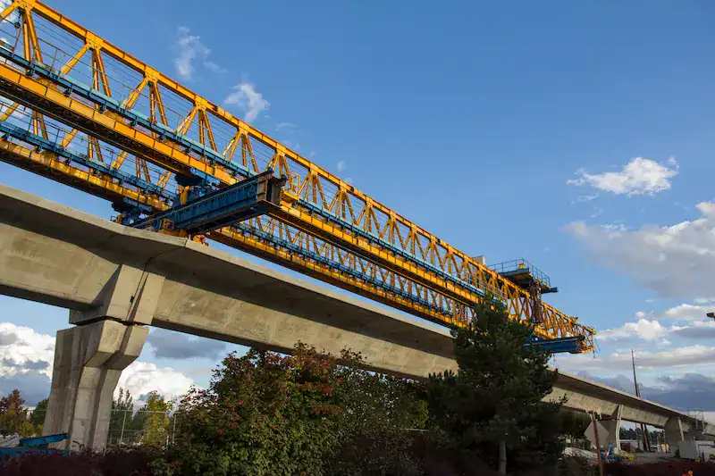
Heavy / HSR | 400t–900t+ | High-speed railway 32m full-span simply-supported box beams, sea-crossing bridges, long-span steel box girders |
How Site Conditions Reduce Effective Capacity
Real-world capacity is always lower than the nameplate rating when site conditions deviate from the design basis:
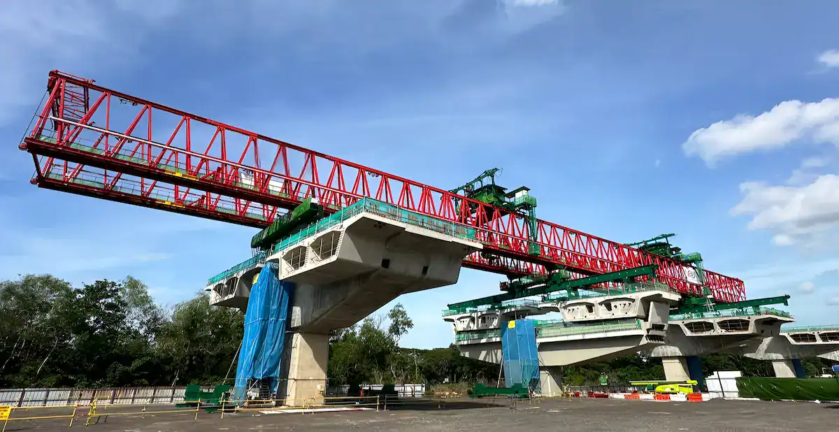
- Curved bridge erection: The beam center of gravity is offset from the girder’s longitudinal axis, introducing torsional loading on the main girder. Select a machine with higher torsional stiffness and lateral stability reserves.
- Skewed bridge erection: Support legs land at different cross-sections, creating uneven reaction forces. A higher safety factor (≥ 1.25) is required.
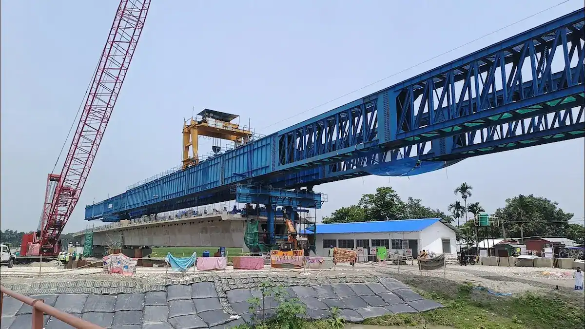
- Tandem lifting (two-girder operation): Asynchronous hoisting causes uneven load distribution. Each machine should be rated for 60%–70% of total beam weight, not 50%, and both units must share a synchronized electrical control system.

How to Calculate Beam Weight
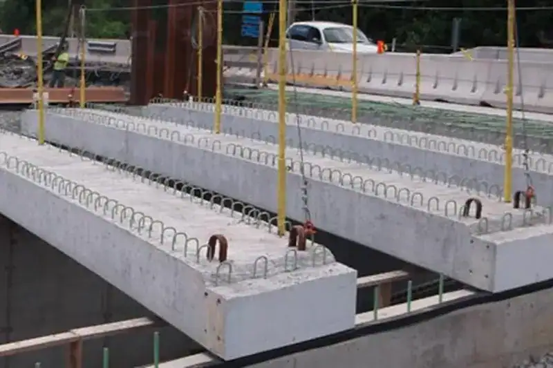
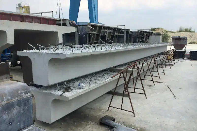
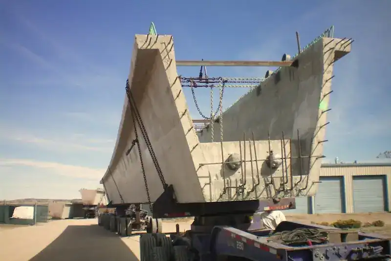
Common Precast Beam Types
Each beam type has distinct sectional properties that affect both its self-weight and how it behaves during lifting:
Beam Type | Section | Advantages | Lifting Considerations |
Box Beam | Closed thin-walled rectangle | High torsional stiffness, ideal for long spans | Highest self-weight; requires wider spreader beam |
T-Beam | T-shaped open section | Simple formwork, cost-effective for standard highway spans | Low lateral stiffness — needs careful rigging balance |
Small Box Beam | Smaller closed section | Balances structural performance with ease of handling | Mid-range weight; versatile for 25m–35m spans |
U-Beam | U-shaped open trough | Low structural depth, noise-reducing profile (urban metro) | Limited lifting access; often requires specialized lifting yokes |

Beam Weight Calculation Formula
The accurate weight of a precast beam is the foundation of every capacity decision:
G = V ×ρ+Gs
Where:
- G= total beam weight (t)
- V= concrete volume (m³) — calculated from the design cross-sectional area × beam length. Obtain this from the structural drawings, not from estimation.
- ρ= reinforced concrete density — use 5–2.6 t/m³ for standard reinforced concrete. For prestressed beams, confirm the mix design density from the batch plant.
- Gs= steel reinforcement and prestressing strand weight (t). Important: If ρ already accounts for reinforcement, do not double-count. If ρ is based on plain concrete, add Gs separately.
Additional items that must be included in the total lifted weight:
- Embedded anchor plates and bearing pads
- End-block concrete (cast after tensioning)
- Lifting yoke, spreader beam, and rigging hardware (can add 2–8t depending on the setup)
Reference Beam Weights by Type and Span
Use this table for preliminary sizing only. Final selection must be based on the design institute’s issued beam schedule for the specific project.
Beam Type | Span (m) | Typical Weight Range (t) | Typical Section Depth (m) |
30m T-Beam | 30 | 80–120 | 2.0 |
40m T-Beam | 40 | 120–160 | 2.5 |
30m Box Beam | 30 | 100–140 | 1.8 |
40m Box Beam | 40 | 140–220 | 2.2 |
HSR Box Beam (Standard) | 32 | 700–900 | 3.0 |
25m U-Beam (Metro) | 25 | 100–130 | 1.6 |
30m U-Beam (Metro) | 30 | 120–180 | 1.8 |
Warning: Never estimate beam weight from a span-to-weight ratio. A 40m box beam can vary from 140t to 220t depending on deck width, prestress design, and concrete density. Approximating kills people.
Determining Required Launching Girder Capacity: Formulas & Safety Factors
Core Selection Formula
The launching girder capacity must satisfy:
Gn ≥ G × K
Where:
- Gn= required rated capacity of the launching girder (t)
- G= heaviest single-beam weight in the project (t)
- K= combined safety factor (dimensionless)
This formula looks simple, but K is not a single number — it is a composite of multiple load amplification effects.
Impact of Dynamic Load Coefficients
During lifting, static beam weight is not the only load the equipment bears. The following dynamic increments must be considered:
- Hoisting Impact:Acceleration during lift-off and speed changes creates dynamic loads. This is typically 1.1 to 1.2 times the lifting load.
- Wind Load Impact:Large beams have significant wind-catching areas. Lateral wind forces shift the center of gravity. This requires higher torsional rigidity and stronger transverse mechanisms.
- Braking Inertia Impact:Inertia from longitudinal or transverse braking converts into horizontal loads. These forces act directly on outriggers and connections. Redundant launching girder capacity is needed to offset this alternating stress.
Understanding the Safety Factor K
K is the product of distinct coefficients, each addressing a specific physical phenomenon:
Coefficient | Symbol | Range | What It Covers |
Dynamic impact factor | φ₁ | 1.10–1.20 | Lifting acceleration at beam lift-off and variable-speed hoisting |
Wind load factor | φ₂ | 1.00–1.10 | Lateral wind pressure on the beam face during hoisting (site-specific) |
Braking inertia factor | φ₃ | 1.00–1.05 | Longitudinal deceleration during trolley travel and cross-shifting |
For most projects, a combined K of 1.10–1.40 is appropriate, broken down by condition:
Operating Condition | Recommended K | Example |
Standard — flat grade, calm weather, straight simply-supported spans | 1.10–1.25 | Highway overpass, rural bridge |
Moderate — gentle curves (R > 500m), light crosswind, minor longitudinal slope | 1.20–1.30 | Mountainous highway, river crossing |
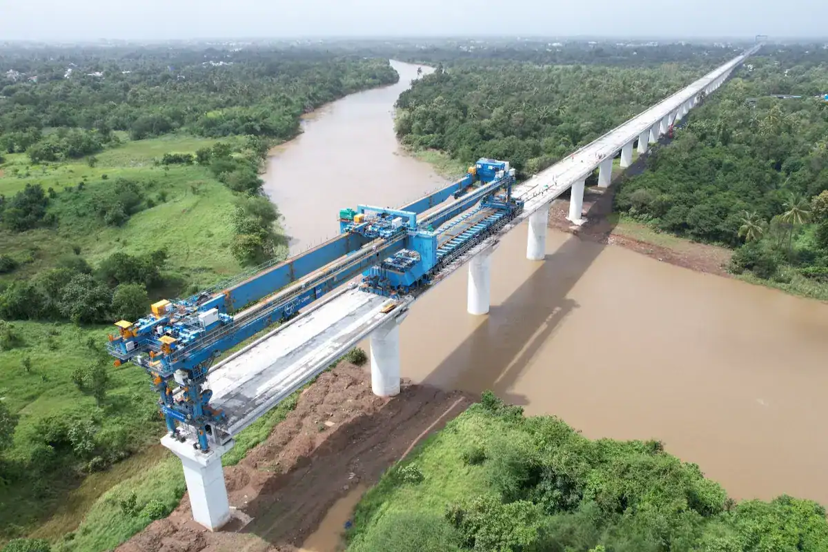
Complex — tight curves (R < 500m), steep grades, high-wind corridor, skewed piers | 1.25–1.40 | Mountain bridge, coastal bridge, HSR |
Worked Examples: Three Real Selection Scenarios
Example 1: 120t Highway T-Beam
Step | Calculation | Result |
Heaviest beam weight (G) | From beam schedule | 120t |
Safety factor (K) | Standard condition | 1.25 |
Required capacity | 120 × 1.25 | 150t |
Recommended selection | 160t launching girder | — |
A 160t-rated machine provides adequate headroom for 40m-span highway T-beam erection while keeping the hoist duty cycle within S3/S4 rating for high-frequency operations (6–8 beams per day).
Example 2: 200t Box Beam
Step | Calculation | Result |
Heaviest beam weight (G) | From beam schedule | 200t |
Safety factor (K) | Moderate condition (curved alignment) | 1.30 |
Required capacity | 200 × 1.30 | 260t |
Recommended selection | 250t–300t launching girder | — |
Box beams have a higher center of gravity and wider deck section than T-beams. The selected machine must also provide enhanced lateral stability — check the manufacturer’s torsional stiffness data.
Example 3: 900t HSR Box Beam
Step | Calculation | Result |
Heaviest beam weight (G) | Standard 32m HSR segment | 900t |
Safety factor (K) | Integrated into specialized design | Pre-engineered |
Required capacity | 900t (minimum rated) | 900t |
Recommended selection | 900t+ purpose-built launching gantry with integrated transporter | — |
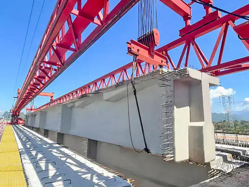
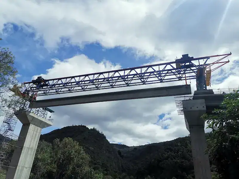
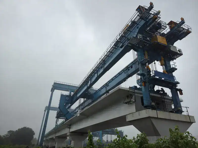
For HSR applications, do not adapt a lower-capacity machine. The 900t-class launching gantry is a specialized system with a girder-transporter integrated design. The safety margin is engineered into the structural design from the start — confirm that the manufacturer provides a full finite element analysis (FEA) report for the specific span configuration and support conditions.
Beyond Beam Weight: 6 Other Critical Factors
Beam weight is the starting point, but these six parameters determine whether the selected machine can actually perform on your site:
Factor | Key Parameter | Impact on Selection |
Bridge Span Length | Maximum span, main girder length | Determines the main girder’s required section modulus and buckling resistance. A 50m span requires roughly 2.5× the bending stiffness of a 30m span for the same beam weight. |
Erection Method | Single-beam, tandem lift, full-span | Dictates spreader beam configuration and whether a conventional launching girder or an integrated transporter-gantry system is needed. Tandem lifts require electrical synchronization between machines. |
Wind & Environment | Gust speed, altitude, temperature extremes | For operational wind speeds above 20 m/s, the machine requires an anemometer interlock and anti-slip anchorages. High-altitude sites (>2,000m) require de-rated motor output. Extreme cold (< -20°C) demands low-temperature-rated hydraulic oil and structural steel with Charpy impact-tested grades. |
Erection Cycle Rate | Beams per day, project deadline | High-cycle projects (8+ beams/day) need variable-frequency drives on all motions and a hoist motor with at least 20% power reserve above calculated demand. Undersized motors trip on thermal overload within the first 3–4 cycles. |
Beam Feeding Method | Rear feeding, side feeding, transporter height | Defines the launching girder’s clearance height above the bridge deck and the leg configuration. Mismatched feeding height is a common cause of on-site modification cost. |
Site Access & Assembly | Crane availability, assembly area | If crane access is limited, a self-launching girder with hydraulic lifting frames may be required instead of a ground-assembled unit. |
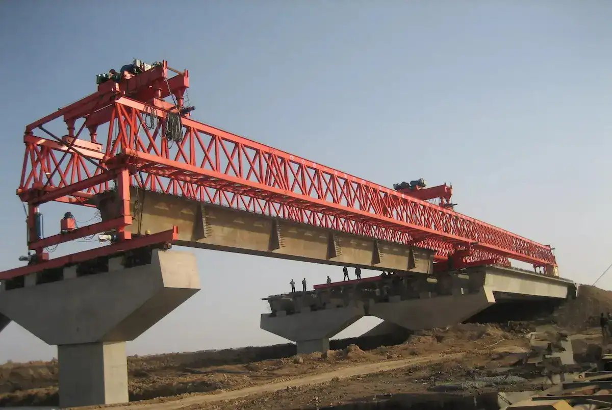
The Cost of Wrong Launching Girder Capacity Selection
A launching girder capacity mismatch doesn’t just reduce performance — it creates compounding costs across every phase of the project:
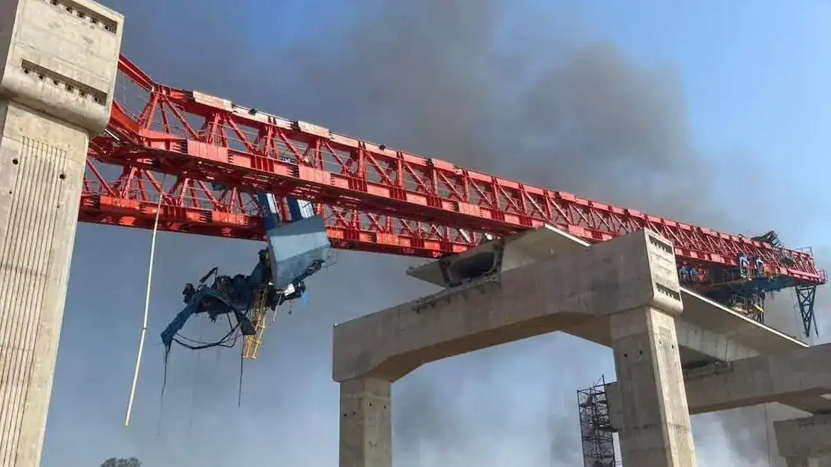
- Safety Accidents from Insufficient Tonnage:When loads approach or exceed limits, stress surpasses material yield points. This causes girder fractures, hoist brake failure, wire rope breakage, or loss of stability. Such failures lead to catastrophic accidents involving equipment destruction and fatalities.
- Accelerated Structural Fatigue:Operating near maximum launching girder capacity causes irreversible stress fatigue in welds, pins, and bolts. Rapidly expanding micro-cracks lead to structural failure long before the design life ends. This significantly increases the risk of equipment scrapping.
- Decreased Construction Efficiency:Low tonnage matching forces power systems (motors, hydraulic stations) to run under heavy loads. This triggers frequent overheat protection or electrical faults. Lack of power reserves forces slower lifting and travel speeds, preventing efficient standardized operations.
- Increased Project Costs:This includes both direct and indirect costs.
- Direct Costs:On-site reinforcement, frequent replacement of wear parts, and high repair fees caused by improper selection.
- Indirect Costs:Work stoppage for rectification due to safety hazards and losses from idle personnel and machinery during breakdowns.
- Schedule Delay Risks:Bridge engineering is highly linear. As core equipment on the critical path, any launching girder performance issue or accident can paralyze the entire line. This triggers severe risks of breach-of-contract compensation.
HSCRANE Launching Girder Product Advantages
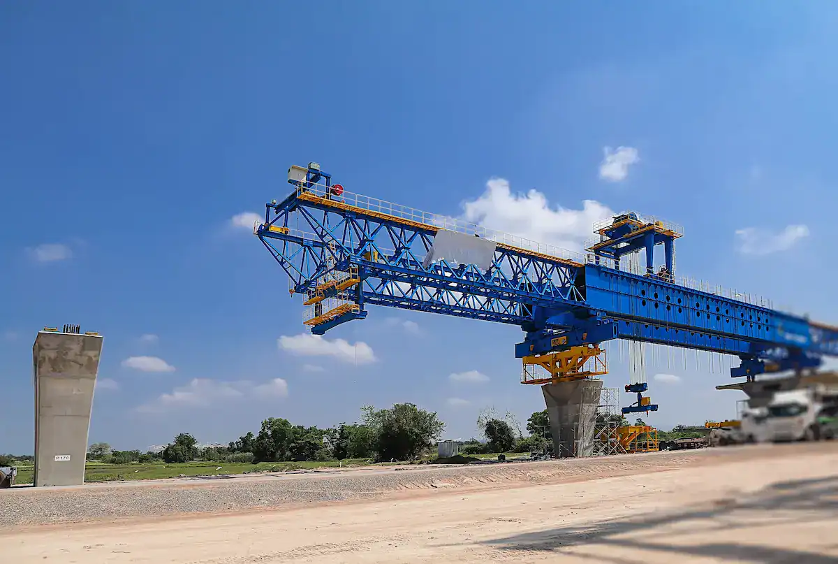
- Multi-Tonnage Customization:HSCRANE can develop and manufacture the full range of launching girders from 80t to 900t. We provide optimized structural designs based on beam type, weight, and slope to ensure precise matching.
- High Safety Design:Products strictly follow ISO, FEM, and GB standards. Systems include automatic overload limits, dual hoist brakes, and outrigger verticality monitoring. Critical welds undergo 100% ultrasonic testing to ensure zero-defect operation.
- Strong Structural Stability:The main girder uses high-strength low-alloy steel in honeycomb or box structures. During high launching girder capacity lifts, deflection control exceeds industry standards. This effectively suppresses load swinging.
- Adaptation to Complex Conditions:For small-radius curves, steep slopes, or tunnel entrances, HSCRANE equipment features flexible legs and hydraulic leveling. It supports skewed installation and longitudinal shifting to widen the working radius.
- Automated and Intelligent Control:Integrated PLC systems and VFDs allow for millimeter-level positioning. Optional remote monitoring tracks stress status and operating parameters in real-time for preventive maintenance.
- Global Project Experience:HSCRANE products serve key infrastructure projects in Southeast Asia, Central Asia, and Africa. We offer reliable lifting support with mature international technical assistance and rapid after-sales service.
HSCRANE Launching Girder Case Study
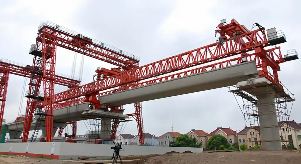
In a large Indonesian highway project, HSCRANE’s 200t guide-beam launching girder successfully erected all standard box beams. This case demonstrates high performance in multinational projects:
- Project Overview:The project involved 40m spans with single beams weighing 180t. Located in a rainforest, the site faced high humidity and heavy rain, testing electrical and metal structures.
- Customized Solution:
- Enhanced Load Margin:For the 180t beams, HSCRANE designed a 200t launching girder capacity. This provided ample safety factors for hoisting inertia in slippery conditions.
- Environmental Adaptation:Electrical cabinets feature IP65 protection. All exposed structural parts received high-standard anti-corrosion coating to ensure zero-fault operation in heat and humidity.
- Construction Performance:The hydraulic system achieved ±5mm positioning accuracy. The modular design shortened disassembly time for relocation, finishing core tasks 15 days ahead of schedule.
- Customer Feedback:The project department praised HSCRANE’s structural stability and technical support. They noted the equipment ensured safety while significantly reducing unit turnover costs.
How to Evaluate a Launching Girder Manufacturer
Evaluation Criteria | What to Verify | Why It Matters |
Custom Engineering Capability | Can the manufacturer provide an FEA report specific to your span, curvature, and beam geometry? Do they offer non-standard leg configurations and spreader beam adaptations? | A standard machine forced onto a non-standard bridge costs more in site modification than the price difference of a custom-engineered solution. Request the finite element calculation package before signing. |
Proven Project Portfolio | Request delivery records for projects matching your tonnage class and site complexity (e.g., 900t HSR, sea-crossing bridges, >3% gradients). | Historical case studies are the most reliable predictor of delivery reliability. Verify with reference calls, not just brochures. |
Field Technical Support | Will the manufacturer deploy a commissioning engineer for assembly supervision, load testing, and operator training? What is the guaranteed response time for breakdown support? | A launching girder is specialized equipment. Unsupervised assembly by a general contractor frequently results in incorrect torque settings on bolted connections and miscalibrated limit switches — both are precursors to accidents. |
International Certifications | ISO9001 (quality management), CE marking / FEM 1.001 compliance, and any country-specific safety certifications required for your project jurisdiction. | Certifications are audited — they verify that the manufacturer’s material traceability, weld procedure qualification, and electrical safety systems meet a documented standard, not just a marketing claim. |
Conclusion
Beam weight is the core benchmark for selecting launching girder capacity, but it is not the only dimension. Scientific selection should follow a “three-in-one” system: static weight as the base, dynamic conditions as variables, and safety redundancy as the guarantee.
- Load Matching:The rated capacity must cover the maximum beam weight. Dynamic increments must be calculated based on hoisting impact and braking inertia.
- Operating Conditions:Consider bridge slopes, curve radii, and wind loads. Use a safety factor of 1.1 to 1.4 to establish performance boundaries.
- Comprehensive Benefits:Proper selection prevents structural fatigue and accidents. It also uses power reserves to speed up cycles and shorten the project schedule.
Choose HSCRANE to Ensure Essential Project Safety
In complex construction environments, a partner with deep engineering experience is vital. HSCRANE provides full-chain solutions from precise capacity calculation to on-site commissioning. Our equipment offers high rigidity and stability, proven on major international projects like those in Indonesia.
[Contact the HSCRANE Technical Team for a Professional Selection Plan]
Extended Reading: Launching Girder Buying Guide
After mastering capacity logic, how do you choose the best equipment? Consider technical parameters, supply chains, and site acceptance. Click the link below to read the Bridge Launching Gantry Buying Guide: 10 Costly Mistakes to Avoid.
[Link: Bridge Launching Gantry Buying Guide: 10 Costly Mistakes to Avoid]
FAQ
Q1: Can the launching girder capacity exactly equal the beam weight?
A1: No. Lifting is not static. Acceleration during hoisting, wind loads, and braking inertia create “dynamic loads.” You must keep a 10% to 25% safety redundancy. Otherwise, the main girder may suffer irreversible deformation or fracture.
Q2: Does the span directly affect capacity selection?
A2: Yes. Increasing the span lengthens the launching girder. Mechanically, a larger span causes faster increases in bending moments and deflection. For large spans, you need equipment with larger cross-sections and higher rigidity, even if the beam weight is the same.
Q3: How do I judge if an old launching girder still meets capacity needs?
A3: A technical assessment is required. Focus on these three points:
- Residual Deformation:Does the girder recover its design camber after unloading?
- Structural Fatigue:Check critical welds and pins for stress cracks using ultrasonic testing.
- Power Performance:Verify motor temperature and brake sliding under rated loads.
This document is for reference only. Specific operations must strictly comply with local laws and regulations and equipment manuals.

Get Expert Advice for Your Bridge Project
Our engineering team brings decades of experience in bridge construction equipment. Let us help you find the right solution.

 Scan to chat