 EN_US
EN_US  Español
  Русский
  العربية
  Português do Brasil
  Français
  Bahasa Indonesia
  Türkçe
  Tiếng Việt
  Bahasa Melayu
  Українська




CE
ISO 9001
SGS
10-Year Structural Warranty
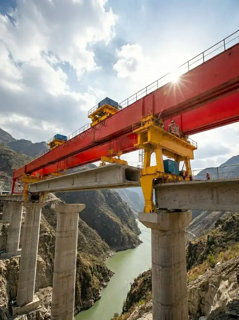
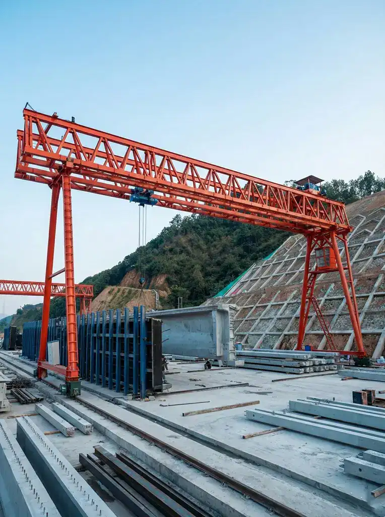
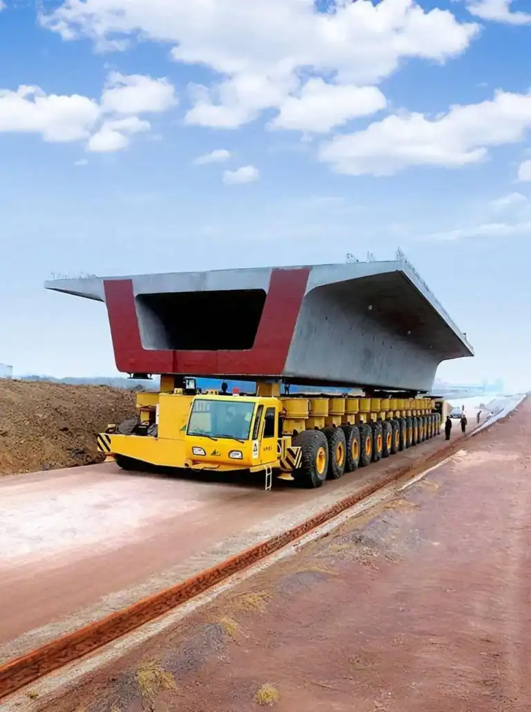
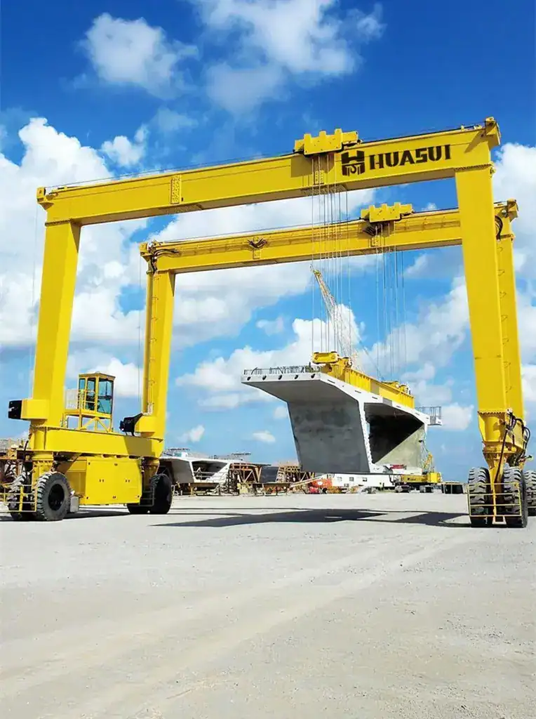
U-Beam Launching Gantry
Specifically designed with specialized spreaders and low-clearance features for the precise installation of U-beams in urban transit systems.
100t - 300t
Capacity
U-Beam Custom
Spreader
Urban Low-Profile
Clearance
25m - 40m
Span
Fast global delivery · 24/7 engineering support · CE & ISO certified
What is a U-Beam Launching Gantry?
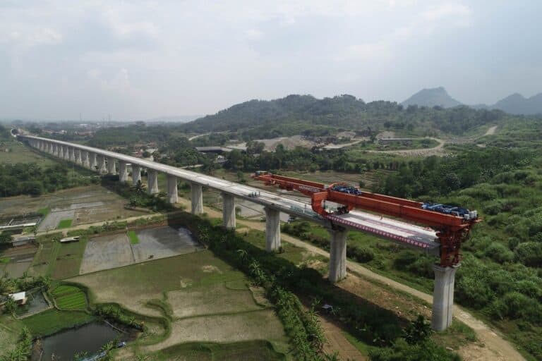
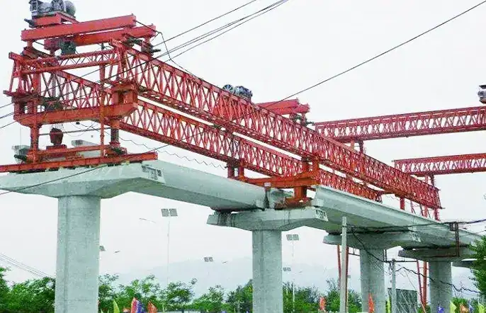
A U-beam launching gantry represents specialized bridge construction equipment spanning between viaduct piers. Railway contractors utilize this massive structural framework to hoist, transport, and accurately position precast concrete U-beams. It guarantees rapid span-by-span erection and superior stability across complex elevated transit projects.
Equipment Overview
A U-beam launching gantry accelerates modern railway viaduct construction significantly. Engineers deploy this heavy-duty precast concrete bridge erector across complex elevated transit networks. You achieve precise span-by-span installation using our advanced U-girder launching machine. The robust railway viaduct construction equipment maneuvers safely over existing highway traffic. Operators align massive concrete sections perfectly via the U-shape beam installation gantry. This reliable bridge launching crane maximizes your daily girder placement rates. Project managers reduce overall bridge completion time substantially through this automated erection technology.
Technical Specifications
| Parameter | Engineering Specification |
|---|---|
| Rated Lifting Capacity | 100t – 300t |
| Applicable Span Length | 25m – 40m |
| Girder Type Compatibility | Thin-Walled U-Beams, Box Girders |
| Longitudinal Moving Speed | 0 – 3.0 m/min |
| Transverse Moving Speed | 0 – 1.5 m/min |
| Hoisting Speed (Full Load) | 0 – 0.8 m/min |
| Maximum Longitudinal Slope | Up to 5% |
| Maximum Transverse Curve Radius | ≥ 500m |
| Power | Diesel generator/power supply |
| Control System Architecture | Wireless remote control/cab |
Application Scenarios
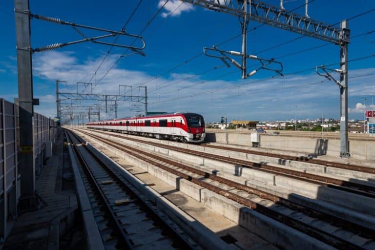
Urban Light Rail Networks
Contractors install metro U-beams rapidly above congested city streets without disrupting daily vehicular traffic.
High-Speed Railway Viaducts
Engineers erect massive span-by-span concrete sections across challenging mountainous terrain and deep river valleys.
Coastal Transit Bridges
Bridge crews construct elevated tracks safely while battling continuous high-velocity ocean winds and corrosive environments.
Why Engineers Choose This Equipment
Feature
Engineering Benefit
Through-Tunnel Navigation Capability
The U-girder launching machine folds main hydraulic support legs autonomously. This allows the gantry to pass through narrow mountain tunnels seamlessly.
Synchronized Three-Dimensional Adjustment
Operators execute precise transverse and longitudinal movements simultaneously. This technology ensures exact precast concrete bridge erector alignment.
Intelligent Pier-Crossing Mechanism
Automated sensors guide the front support column during complex forward progression sequences. You cross elevated bridge piers safely and efficiently.
Aerodynamic Truss Structure
Engineers optimize the main structural framework to minimize dangerous wind loads. The bridge launching crane withstands severe coastal gales during operation.
Customized U-Beam Spreaders
Specialized lifting clamps match specific U-shape concrete profiles perfectly. They secure thin-walled webs firmly without causing structural damage.
Real-Time Load Monitoring
Dynamic force sensors track weight distribution across all lifting points continuously. The central system prevents dangerous asymmetrical overloading immediately.
Frequently Asked Questions
How does the gantry cross bridge piers on high-gradient longitudinal slopes?
The machine utilizes hydraulic jacking cylinders and heavy-duty friction rollers. The PLC synchronizes forward movement while maintaining strict horizontal leveling across 5% longitudinal gradients.
Can the lifting spreaders accommodate varying U-beam web thicknesses?
Yes. Engineers integrate adjustable hydraulic clamping systems into the specialized U-beam spreaders. You modify the contact pads quickly to secure different thin-walled concrete profiles safely.
What safety systems prevent structural overturning during forward progression?
The gantry employs dynamic counterweights and continuous center-of-gravity monitoring. Redundant rear anchor clamps lock onto the previously installed girder, preventing catastrophic forward tipping completely.
How do operators control precise beam positioning during final placement?
Technicians use remote industrial controllers featuring millimeter-level micro-adjustment functions. Proportional hydraulic valves regulate hoisting winches to ensure exact transverse and longitudinal U-beam alignment.
What maintenance protocols ensure reliable hydraulic cylinder performance?
Technicians must replace hydraulic fluid filters every 500 operating hours. Maintenance teams inspect load-bearing seals regularly to prevent dangerous pressure drops during heavy lifting operations.
What is the typical lead time for delivery?
Standard lead time is 30-45 days depending on configuration and current production schedule. We provide a firm delivery date with every quotation.
Do you provide installation and commissioning support?
Yes. Our engineering team can travel to your project site to supervise installation, provide training for your crew, and commission the equipment. Remote video support is also available.
What warranty do you offer?
All our structural equipment comes with a 10-year structural warranty and 2-year comprehensive warranty covering manufacturing defects. Extended warranty options are available.
What shipping methods are available?
We ship worldwide via container (FCL/LCL), flat rack for oversized components, or RO-RO for self-propelled equipment. FOB, CIF, and DAP terms are available.
Do you offer custom engineering solutions?
Absolutely. Our engineering team works with your project specifications to customize span length, lifting capacity, and control systems to meet your exact bridge construction requirements.
Didn't find your answer? Contact our engineers →


Get a Quote Within 24 Hours
Fill out the form below and our engineering team will respond with a detailed quotation.
Related Equipment
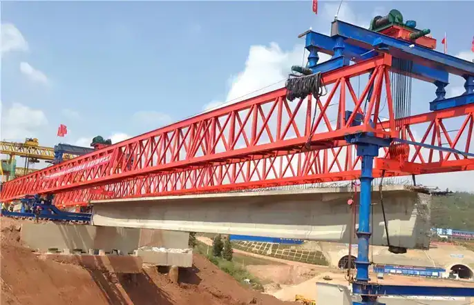
Highway Launching Gantry
A highly efficient and robust bridge erection solution, engineered for the safe and rapid launching of precast T-beams and I-beams in highway infrastructure projects.
View Details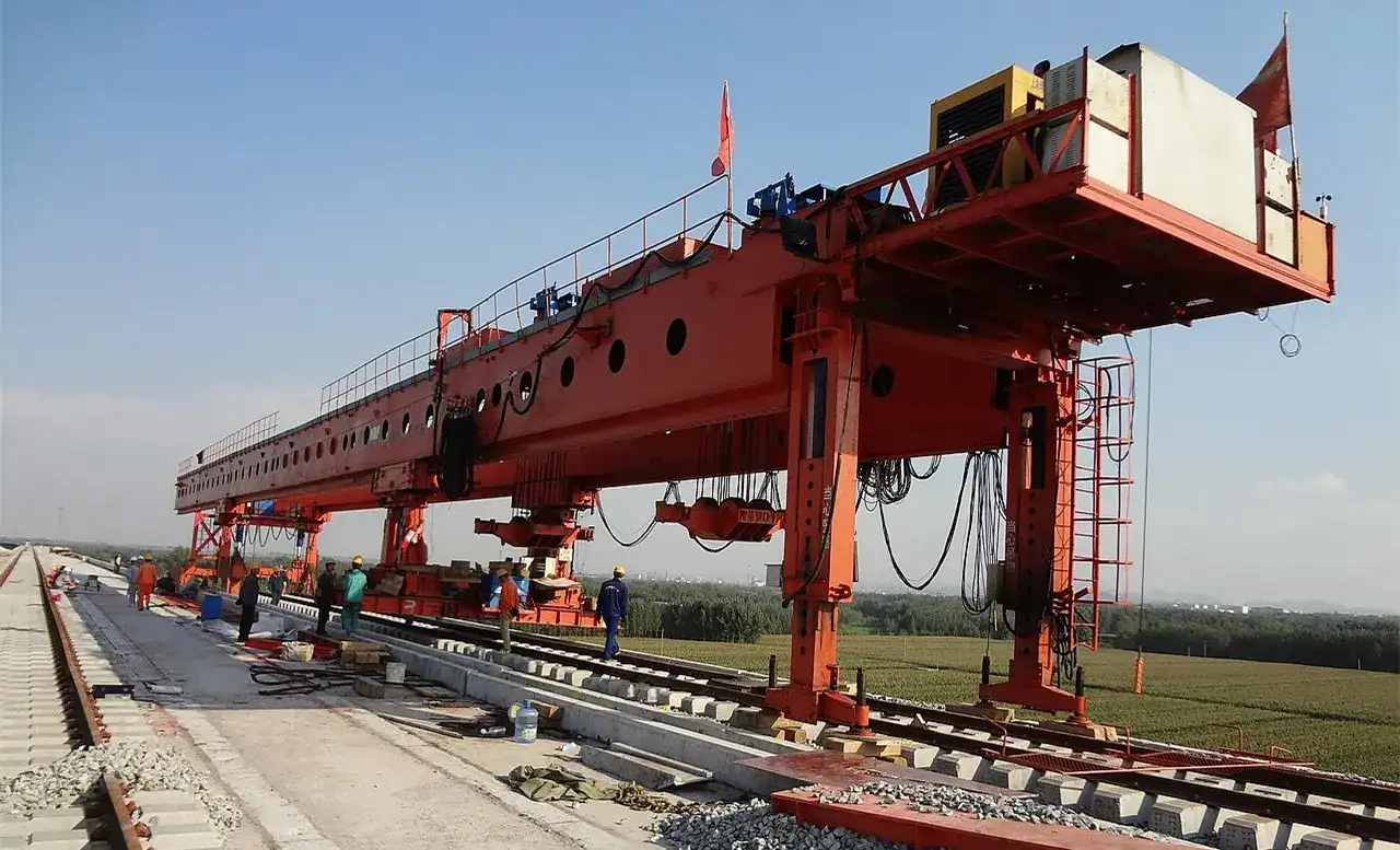
Road-Rail Dual-Use Gantry
Highly versatile launching equipment capable of seamless transition between road and railway bridge construction modes.
View Details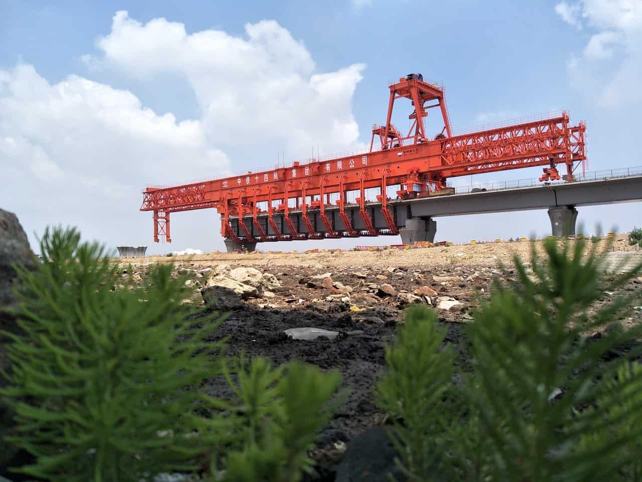
Movable Scaffolding System
A self-launching formwork system designed for cast-in-situ concrete bridges, eliminating the need for ground scaffolding.
View Details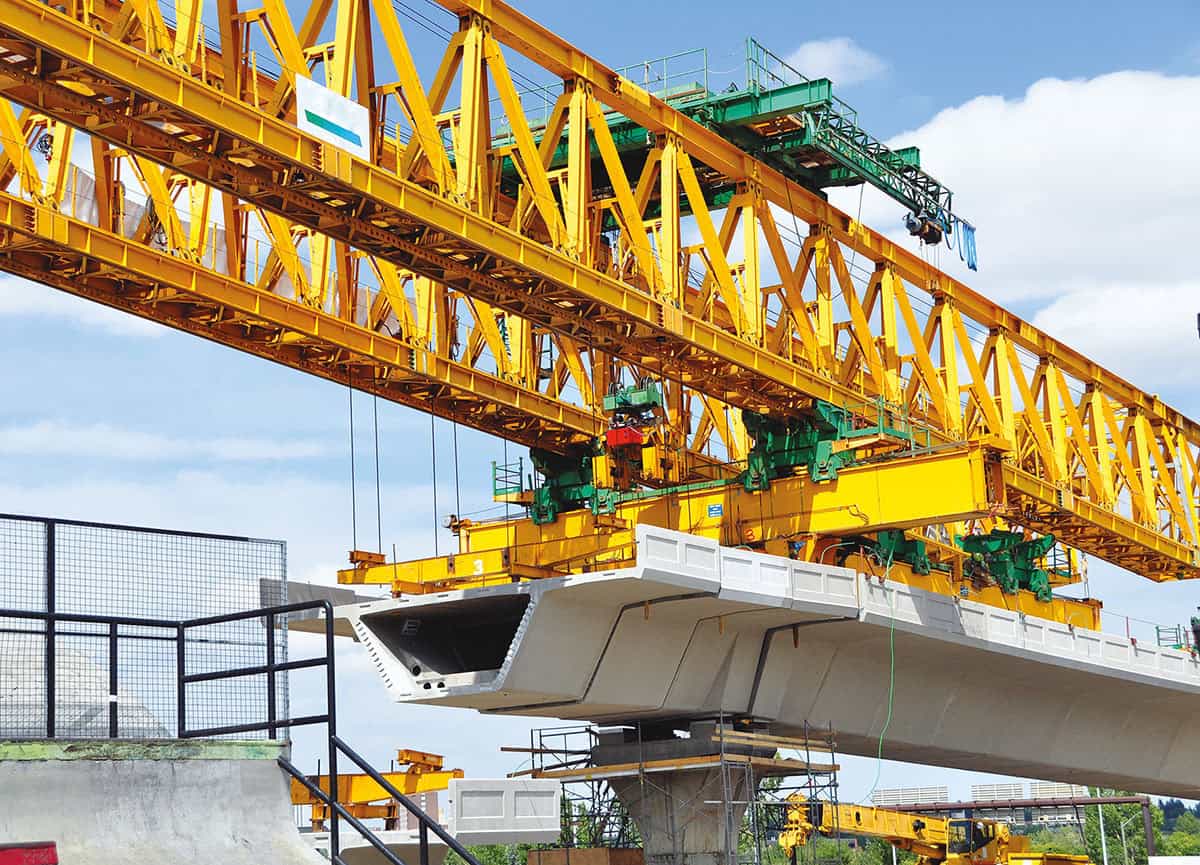
Segmental Launching Gantry
Engineered for the rapid and precise in-situ assembly of precast concrete segments for long-span bridge construction.
View Details Scan to chat