 EN_US
EN_US  Español
  Русский
  العربية
  Português do Brasil
  Français
  Bahasa Indonesia
  Türkçe
  Tiếng Việt
  Bahasa Melayu
  Українська




CE
ISO 9001
SGS
10-Year Structural Warranty
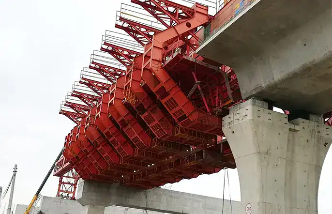
Movable Scaffolding System
A self-launching formwork system designed for cast-in-situ concrete bridges, eliminating the need for ground scaffolding.
30m - 50m
Span
Hydraulic Adjustable
Formwork
Self-Launching
Advance
Cast-in-Situ
Application
Fast global delivery · 24/7 engineering support · CE & ISO certified
What is a Movable Scaffolding System?
A movable scaffolding system functions as a self-supporting, automated framework for cast-in-situ bridge construction. Structural engineers utilize this specialized machinery to support wet concrete pouring between viaduct piers. It eliminates traditional ground falsework, guaranteeing rapid span-by-span construction across deep valleys, rivers, and congested urban highways.
Equipment Overview
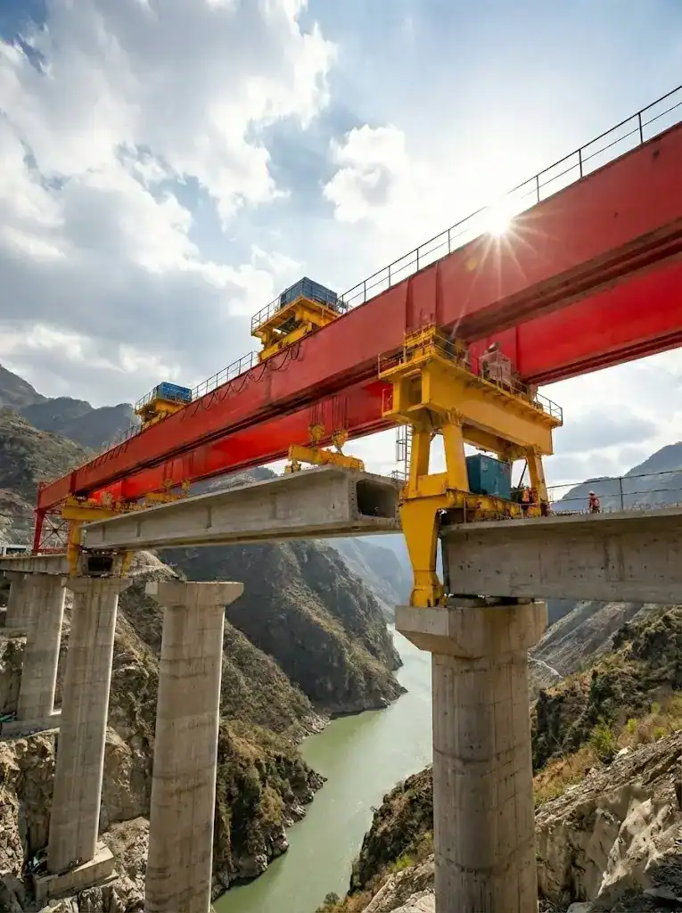
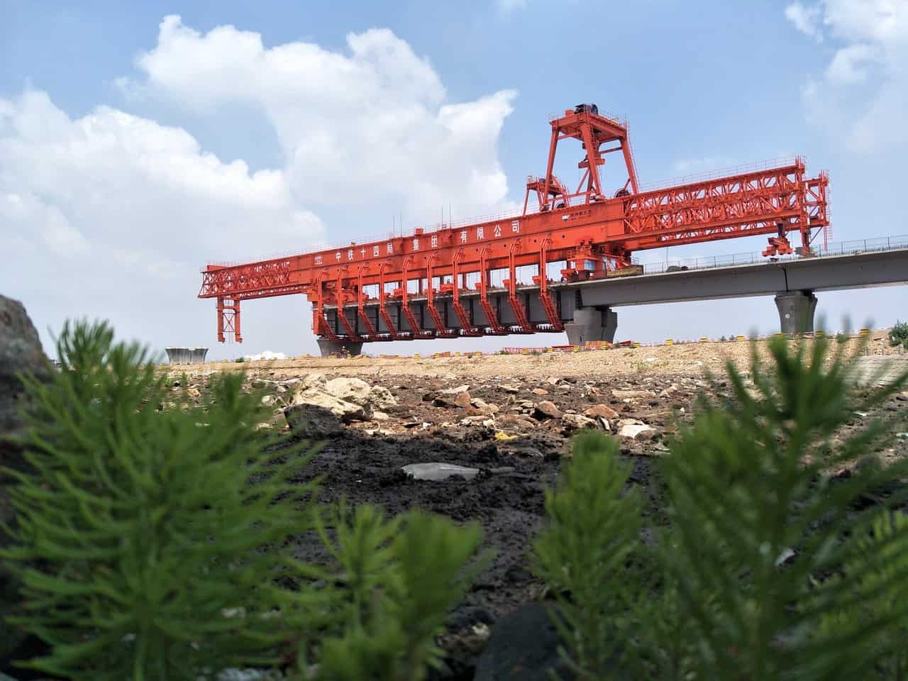
A Movable scaffolding system accelerates cast-in-situ concrete bridge construction significantly. Engineers deploy this overhead bridge construction equipment across complex viaduct projects worldwide. The self-launching falsework advances automatically between bridge piers without requiring ground support. Operators pour continuous concrete spans efficiently using this advanced cast-in-situ formwork system. You reduce project completion times drastically through rapid mechanized formwork relocation. Our robust MSS bridge builder handles massive wet concrete loads safely over deep valleys. This underslung movable scaffolding guarantees precise span-by-span concrete structural alignment.
Technical Specifications
| Parameter | Engineering Specification |
|---|---|
| Structural Configuration | Overhead (Top-Supported) / Underslung (Bottom-Supported) |
| Standard Span Range | 30m – 50m |
| Maximum Concrete Pouring Capacity | 800t – 1500t per span |
| Typical Production Cycle | 10 – 14 Days per span |
| Longitudinal Advancing Speed | 1.5 m/min |
| Maximum Longitudinal Gradient | Up to 5% |
| Minimum Horizontal Curve Radius | ≥ 1500m |
| Main Girder Deflection Ratio | ≤ L/700 (Under maximum concrete load) |
| Hydraulic System Pressure | 25 MPa – 31.5 MPa |
| Applicable Cross-section | Single-compartment single-box / Single-compartment double-box |
| Advancing Method | Self-Launching |
| Wind Resistance | Up to Beaufort 12 |
Application Scenarios

Deep River Valley Viaducts
Contractors cast continuous concrete bridge spans safely without erecting massive ground-based scaffolding towers.

Urban Elevated Highways
Operators execute cast-in-situ pouring operations efficiently above congested city streets without disrupting traffic flow.

Coastal Cross-Sea Bridges
Engineers utilize the wind-resistant formwork system to construct heavy railway bridges over active marine environments.
Why Engineers Choose This Equipment
Feature
Engineering Benefit
Automated Longitudinal Launching
Hydraulic cylinders advance the entire movable scaffolding system autonomously to the next bridge pier.
Adaptable Formwork Geometry
Engineers adjust the internal steel formwork easily to accommodate varying box girder cross-sections perfectly.
Ground-Independent Operation
The overhead bridge construction equipment transfers all concrete pouring loads directly onto existing bridge columns.
Accelerated Pouring Cycles
Construction crews complete an entire 50-meter cast-in-situ concrete span within a rapid 12-day production cycle.
Integrated Safety Enclosures
The cast-in-situ formwork system features fully enclosed operational walkways. This protects workers in high-wind environments.
Precise Camber Control
Adjustable hydraulic jacks manipulate the self-launching falsework exactly to counteract heavy wet concrete deflection.
Frequently Asked Questions
What span lengths can the standard self-launching falsework construct efficiently?
We engineer structural frameworks to cast spans ranging from 30 to 60 meters. Technicians customize the main girders to handle specific project span variations while maintaining strict deflection tolerances.
How does the system handle longitudinal gradients during forward advancement?
The hydraulic launching mechanism incorporates multi-directional sliding bearings and automated leveling jacks. This technology allows the machinery to advance safely across longitudinal gradients up to 5%.
Can the internal formwork adapt to different box girder web thicknesses?
Yes. Engineers integrate modular steel panels and adjustable hydraulic struts into the core formwork. Crews modify the internal geometry quickly to accommodate changing web dimensions between consecutive bridge piers.
What safety limits govern the hydraulic cylinders during the pouring phase?
High-capacity pressure sensors monitor the vertical support jacks continuously. Mechanical locking nuts secure the hydraulic cylinder rams physically, preventing any dangerous structural settling under heavy wet concrete loads.
How do operators relocate the equipment around severe horizontal curves?
The overhead main girders feature articulated transverse adjustment hinges. Hydraulic lateral shifting mechanisms align the entire scaffolding precisely to match demanding highway alignment curves down to a 400-meter radius.
What is the typical lead time for delivery?
Standard lead time is 30-45 days depending on configuration and current production schedule. We provide a firm delivery date with every quotation.
Do you provide installation and commissioning support?
Yes. Our engineering team can travel to your project site to supervise installation, provide training for your crew, and commission the equipment. Remote video support is also available.
What warranty do you offer?
All our structural equipment comes with a 10-year structural warranty and 2-year comprehensive warranty covering manufacturing defects. Extended warranty options are available.
What shipping methods are available?
We ship worldwide via container (FCL/LCL), flat rack for oversized components, or RO-RO for self-propelled equipment. FOB, CIF, and DAP terms are available.
Do you offer custom engineering solutions?
Absolutely. Our engineering team works with your project specifications to customize span length, lifting capacity, and control systems to meet your exact bridge construction requirements.
Didn't find your answer? Contact our engineers →


Get a Quote Within 24 Hours
Fill out the form below and our engineering team will respond with a detailed quotation.
Related Equipment
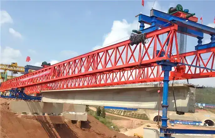
Highway Launching Gantry
A highly efficient and robust bridge erection solution, engineered for the safe and rapid launching of precast T-beams and I-beams in highway infrastructure projects.
View Details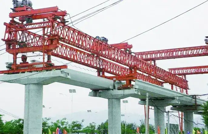
U-Beam Launching Gantry
Specifically designed with specialized spreaders and low-clearance features for the precise installation of U-beams in urban transit systems.
View Details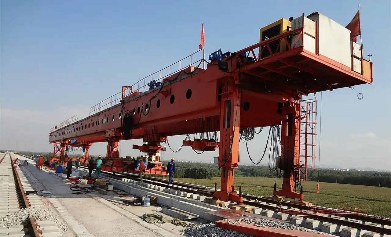
Road-Rail Dual-Use Gantry
Highly versatile launching equipment capable of seamless transition between road and railway bridge construction modes.
View Details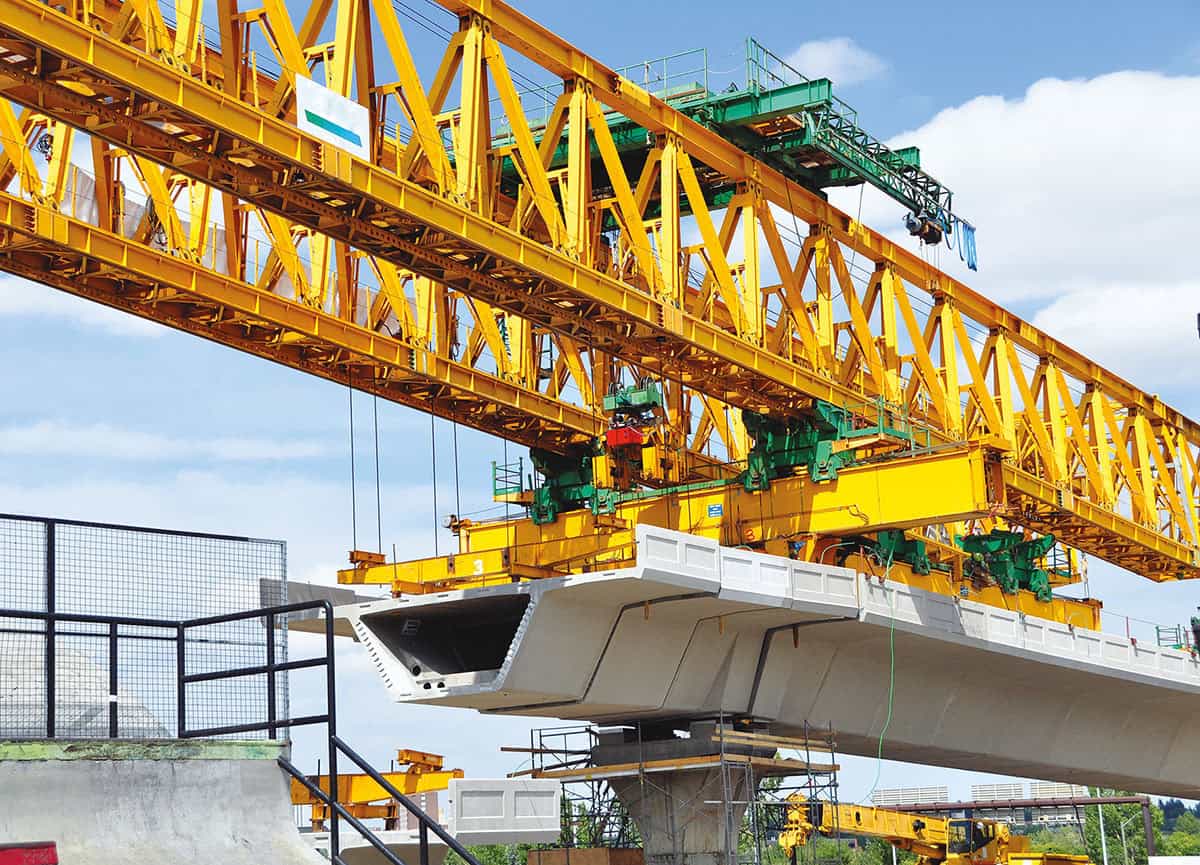
Segmental Launching Gantry
Engineered for the rapid and precise in-situ assembly of precast concrete segments for long-span bridge construction.
View Details Scan to chat