 EN_US
EN_US  Español
  Русский
  العربية
  Português do Brasil
  Français
  Bahasa Indonesia
  Türkçe
  Tiếng Việt
  Bahasa Melayu
  Українська

 Technical Insight
Technical Insight
Bridge Launching Gantry Movement System Design: Key Technologies & Principles
Overview
This paper systematically analyzes the design and operation of bridge launching gantry longitudinal and transverse systems. We focus on the structural components, drive methods, and coordination workflows of these movement systems. The study explains key technologies like synchronous control, load distribution, and safety protection. These elements play a core role in improving bridge construction efficiency and safety. We also propose optimized designs and solutions for common problems in complex conditions. The article highlights HSCRANE’s technical advantages in the bridge launching gantry field. These include customized design, high-precision control, and reliable structural performance. Our goal is to help customers achieve efficient and safe bridge construction.
The bridge launching gantry is the core equipment for bridge construction tasks. It handles the critical duties of beam transport and precision installation. The longitudinal and transverse systems determine the equipment’s travel, positioning, and adjustment capabilities. These systems directly impact construction efficiency and operational safety. Different projects like high-speed rails, highways, and river crossings have unique requirements. They demand high operational precision, stability, and adaptability from the equipment. Therefore, the design of these movement systems is vital for success.
Design Principles of Bridge Launching Gantry Longitudinal Systems
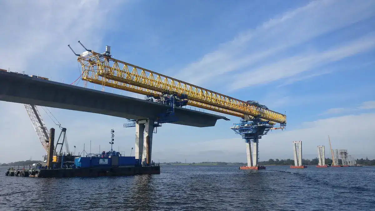
The longitudinal system serves as the core module for advancing the entire machine and accurately positioning the beam. Consequently, its design directly impacts construction efficiency, stability, and safety. To be effective, an efficient system must achieve a precise balance between structural design, power matching, and control precision to meet the diverse needs of various bridge construction environments.
Basic Components of the Longitudinal System
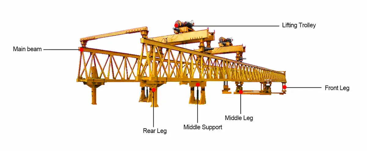
To understand how this system functions, it is essential to look at its three primary pillars:
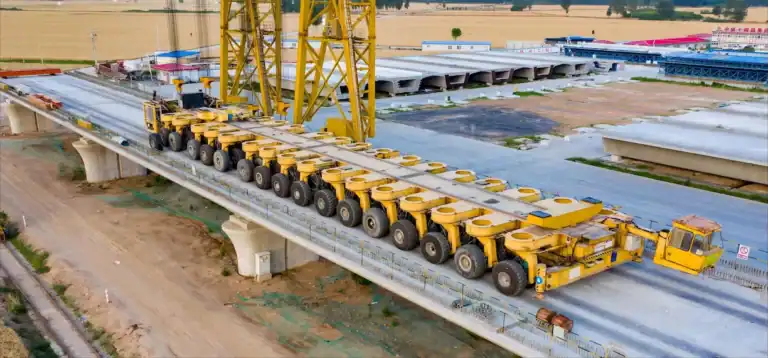
- Travel Mechanism (Wheel Sets/Rails):First and foremost, the travel mechanism provides the physical foundation for all longitudinal movement. This assembly typically consists of wheel sets, rails, and heavy-duty support structures. Furthermore, the precise matching between wheels and rails is what ensures smooth operation and long-term durability. During the design phase, engineers focus specifically on wheel pressure distribution and rail strength in order to avoid “rail gnawing” or dangerous deviations during travel.
- Drive Unit (Motor + Gearbox): In coordination with the mechanical structure, the drive system utilizes high-torque motors paired with specialized gearboxes to transmit power efficiently. Specifically, a proper gear ratio design is crucial because it ensures smooth starts even when the gantry is operating under maximum heavy loads. Moreover, these drive units must be engineered with a strong overload capacity so that they can adapt to the unpredictable resistances found in complex construction environments.
- Control System: Finally, the control system acts as the “brain” of the entire longitudinal operation. It typically integrates PLC (Programmable Logic Controller) and VFD (Variable Frequency Drive) technologies to manage movement. By monitoring the equipment’s status in real-time, the system can dynamically adjust speed and torque. As a result, this high level of oversight ensures that the bridge launching gantry remains stable, synchronized, and safe throughout its journey.
Longitudinal Operating Mechanism
Longitudinal movement is a complex process of dynamic balance rather than simple displacement.
Workflow for Beam Forward Movement
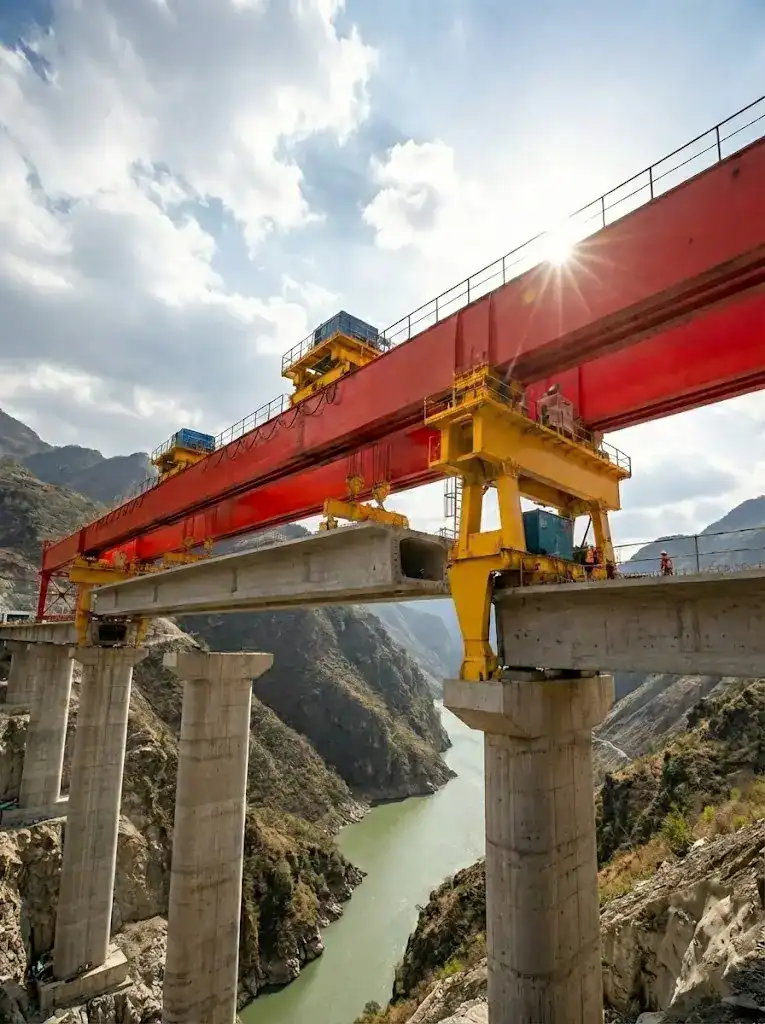
During span-crossing operations, the system drives the main beam forward along the rails. The typical process includes:
- Self-balance Confirmation: Checking the support status of the rear and front legs.
- Power Intervention:Multiple drive motors start synchronously under VFD control.
- Span Crossing:The cantilever extends forward until the front leg reaches the next pier.
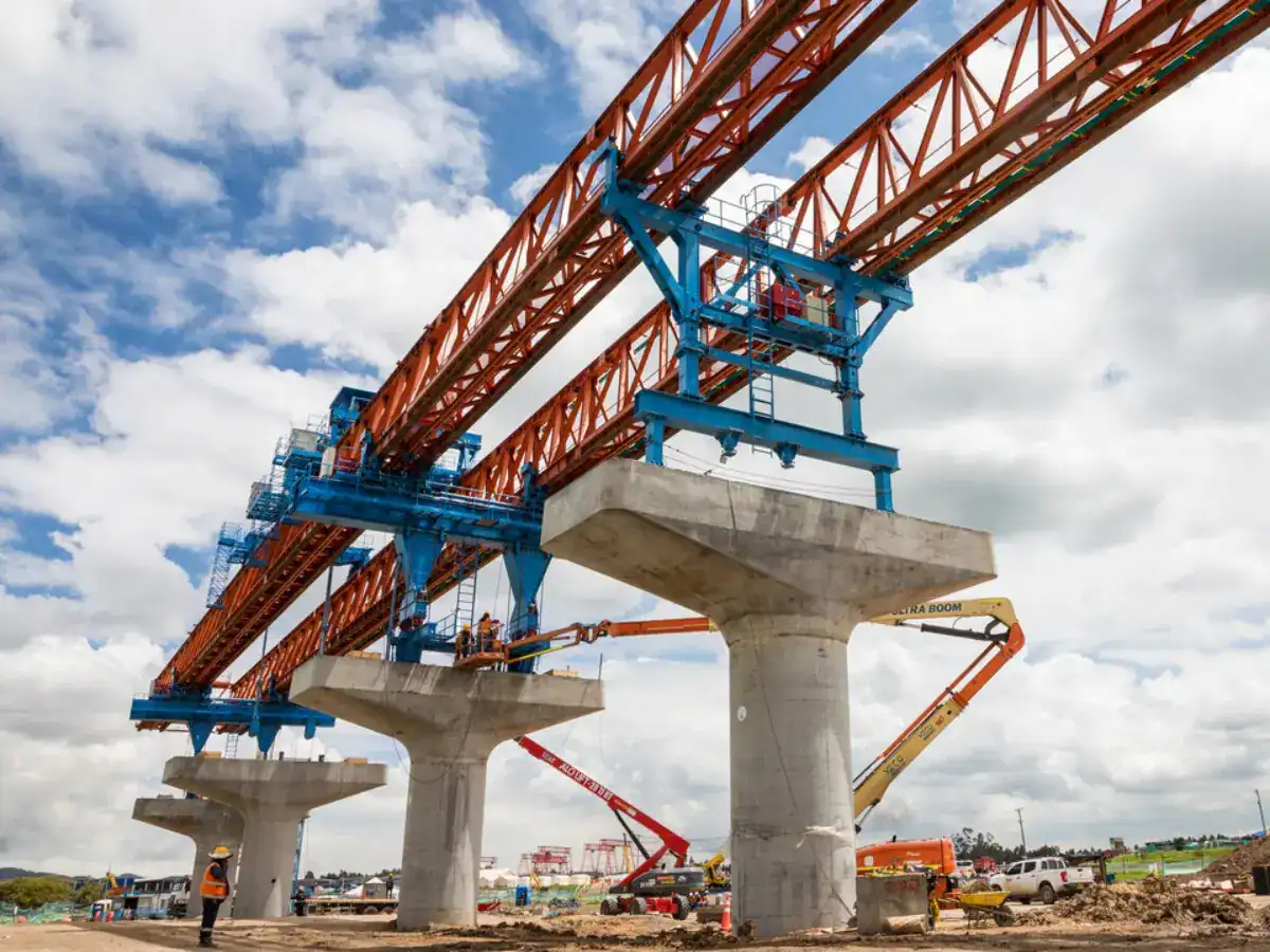
HSCRANE utilizes “Lightweight Lead Beam + Hydraulic Middle Leg Alternating Support Technology.” During crossing, precise counterweights and hydraulic stepping ensure cantilever deflection stays within safe limits. This effectively prevents “nose-diving” accidents.
Load Distribution and Stress Analysis
The center of gravity changes constantly during longitudinal movement. Designers use Finite Element Analysis (FEA) to simulate the worst-case scenarios:
- Cantilever Stress: Balancing the torque between the rear counterweight and the front structure is the core design challenge.
- Wheel Pressure Calculation:We precisely calculate maximum wheel pressure during dynamic operation. This ensures it stays within the bridge’s load-bearing limits.
Synchronous Control Principle
Due to the large span and high self-weight, left and right travel must be perfectly synchronized. HSCRANE uses a closed-loop control system. Encoders provide real-time feedback on motor speed and position. If a deviation occurs, the system automatically adjusts the VFD frequency. This eliminates “crabbing” and prevents additional structural stress.
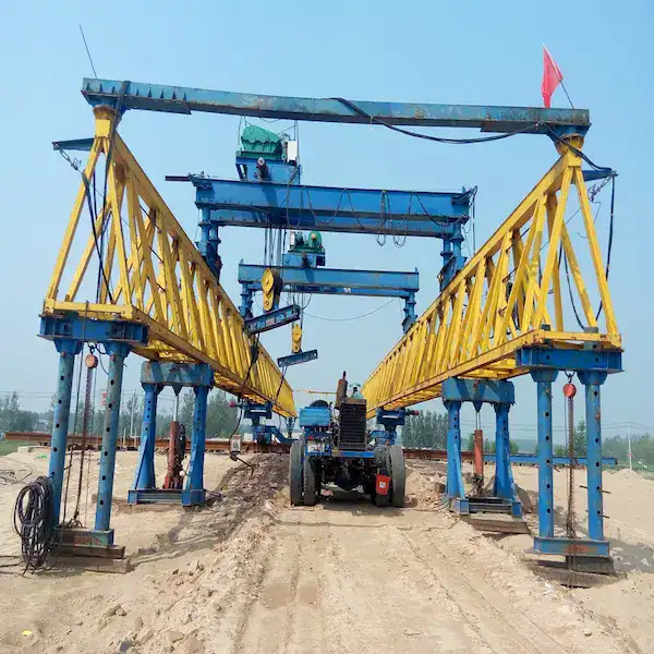
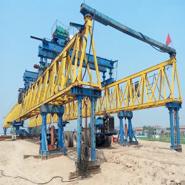
Conquering the Void: Safe Launching Mechanics & Anti-Overturning Design
The most hazardous phase of bridge construction is the “launching” stage, where the gantry must propel itself across the empty span between piers. A minor imbalance here can lead to catastrophic overturning.
- The HSCRANE Solution:We engineer our launching gantries with a precision-calculated Lightweight Launching Nose and an active counterweight management system. During the longitudinal movement, the PLC continuously calculates the shifting Center of Gravity (CoG). Combined with our Hydraulic Stepping Middle Legs, the system ensures the maximum cantilever deflection remains strictly within safety margins, guaranteeing zero risk of tipping even at maximum outreach.
Mastering Slopes: 3D Hydraulic Leveling System
Real-world bridge alignments are rarely perfectly flat; they feature significant longitudinal and cross slopes. Moving a 900-ton concrete girder on a 5% slope using standard wheels will inevitably cause uncontrolled sliding.
- The HSCRANE Solution:Our transverse and longitudinal movement systems are equipped with a 3D Hydraulic Leveling System. Featuring universal spherical hinges and multi-stage hydraulic cylinders on every support leg, the operator can achieve absolute machine leveling with a single button press. This neutralizes gravitational side-pull on gradients, ensuring the VFD motors drive the gantry forward without fighting severe frictional binding or slipping.
Key Design Parameters
The following parameters determine the operational performance of the longitudinal system:
Key Parameter | Design Requirements and Standards |
Travel Speed | Usually 0.5-3.0 m/min; supports stepless speed regulation for smooth starts. |
Travel Precision | Longitudinal positioning error must be within ±10mm for precise bearing alignment. |
Drive Power Matching | Requires a 1.2-1.5 safety power reserve to handle wind and slope resistance. |
Anti-slip & Braking | Must include hydraulic anti-slip devices and fail-safe brakes for emergency locking. |
Design Principles of Bridge Launching Gantry Transverse Systems
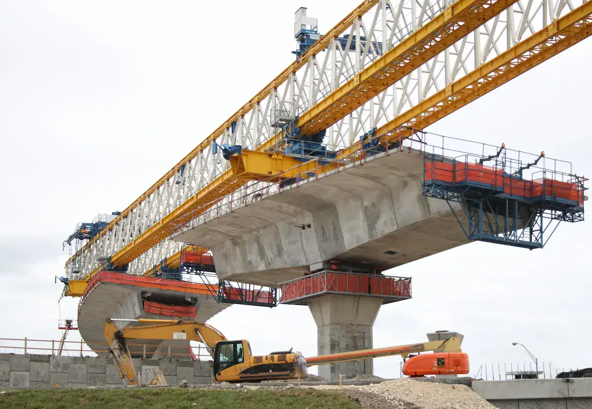
The bridge launching gantry transverse system is used for precise lateral adjustment of the beam. It is the key link for alignment and installation. Compared to longitudinal systems, transverse movement requires higher precision and stability. The design must balance structural reliability, control accuracy, and adaptability to ensure safe lateral positioning.
Structural Components of Transverse Systems
Transverse systems are typically installed at the bottom of the front, middle, and rear support legs. They consist of these key parts:
Transverse Rails and Sliding Devices: Rails span across the abutments or piers. Sliding devices use high-strength tracks or heavy-duty roller sets. To reduce friction, modern designs use a composite pair of stainless steel plates and PTFE (Teflon) sliders. This reduces the friction coefficient below 0.05. It allows smooth movement of 1,000-ton beams with minimal hydraulic thrust, preventing “crawling” or sticking.
Drive Systems (Hydraulic or Electric):
- Hydraulic Drive:Ideal for ultra-heavy beams. It uses synchronous hydraulic cylinders for powerful and stable pushing.
- Electric Drive:Uses motors and gearboxes to drive racks and pinions or chains. It is fast and easy to maintain, making it the mainstream choice for small to medium gantries.
Guiding and Limiting Devices: Lateral guide wheels prevent skewing during movement. Physical limit blocks and electronic proximity switches provide double insurance against derailment.

Transverse Operating Mechanism
- Lateral Adjustment Process:Once the beam is longitudinally in place, the transverse system activates. The drive unit moves the beam slowly along the rails for precise alignment. This requires low-speed operation and real-time monitoring for fine-tuning.
- Multi-point Synchronous Control: Transverse movement involves multiple support points acting together. PLC control and sensor feedback regulate each drive unit. This ensures all support points stay synchronized, avoiding structural stress or jamming caused by lag.
- Stability Control Principles: As the beam moves laterally, the center of gravity shifts. Designers optimize support layouts and structural rigidity. The control system performs dynamic adjustments to maintain balance and safety.
Design Challenges
- Eccentric Loading:Uneven force or installation errors can cause eccentric loads. Designs address this by adding support points, optimizing structural stiffness, or introducing automatic leveling systems.
- Lateral Precision Control: High-speed rail and large-scale bridges require extreme accuracy. High-precision sensors, closed-loop systems, and micro-adjustment technology significantly improve positioning quality.
- Wind Resistance and Anti-overturning: For river, sea, or high-altitude work, the system must handle high wind loads. Enhanced structural design, wind-bracing devices, and optimized CoG layouts reduce tipping risks.
Expert Tip: In curved or skewed bridge construction, transverse rails are not perfectly parallel. The system must provide angular compensation.
HSCRANE gantries feature a 3D Hydraulic Leveling System. Each leg bottom has universal ball joints and multi-stage cylinders. Even on sloped bridge decks, the machine achieves absolute leveling with one click to prevent deviation.
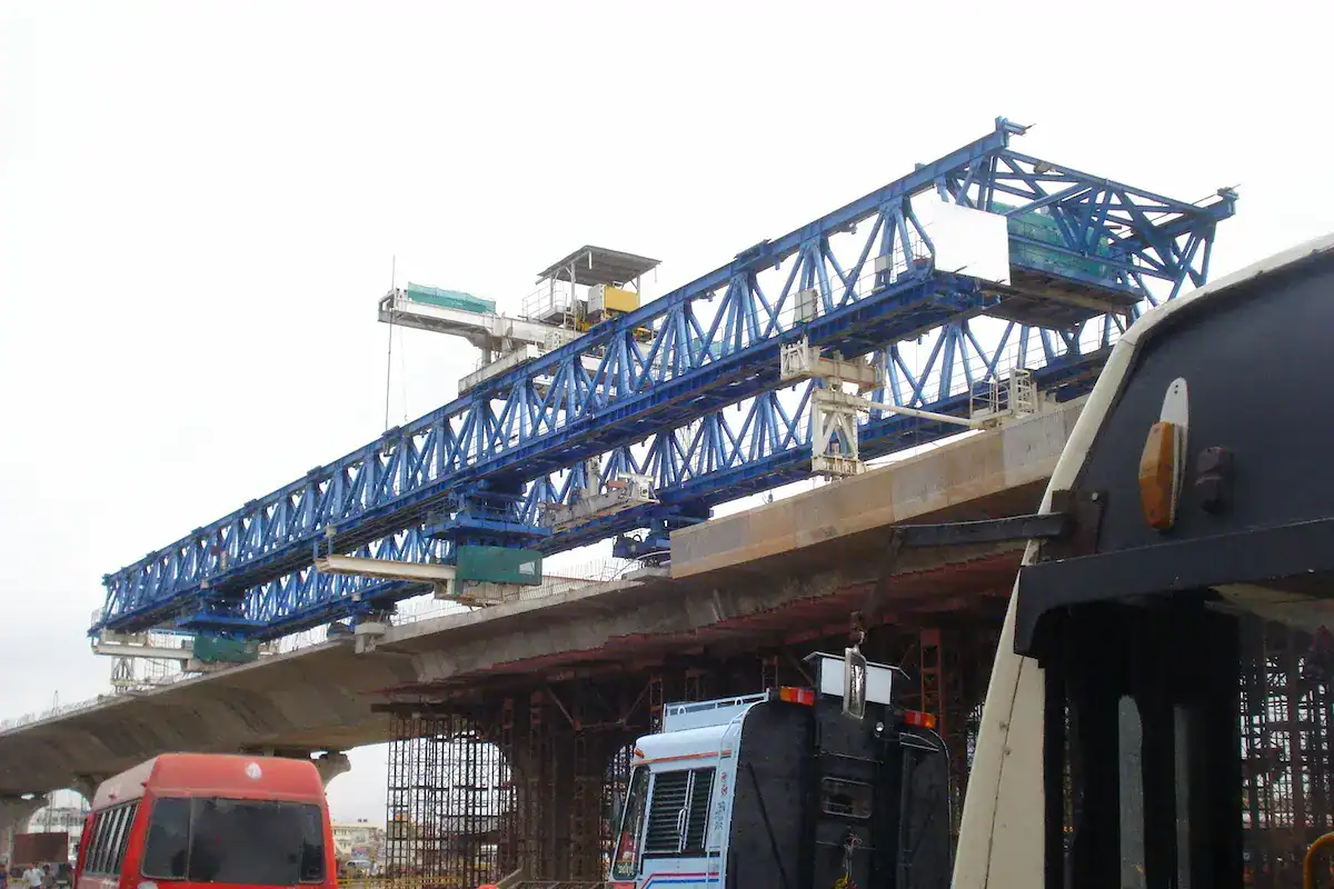
Collaborative Mechanism of Longitudinal and Transverse Systems
To control the process from transport to installation, the longitudinal and transverse systems must work in harmony. Their coordination in timing and logic is the key to construction efficiency.
Module | Description | Technical Points | Practical Role |
Coordination Workflow | Move beam longitudinally to target area, then use transverse system for fine alignment. | Phased control (Travel → Decelerate → Position → Fine-tune). | Improves efficiency; ensures fast and accurate beam seating. |
Automated Linkage | PLC + VFD control coordinates movement and state switching. | Multi-drive sync; real-time feedback; smart mode switching. | Enhances stability; reduces human error; improves safety. |
Error Correction | Sensors detect position deviations and automatically trigger corrections. | Laser ranging; displacement sensors; closed-loop control. | Guarantees installation precision for high-standard bridges. |
Through collaborative design and intelligent control, the bridge launching gantry achieves high-precision beam installation in complex conditions. This provides a reliable technical foundation for modern bridge construction.
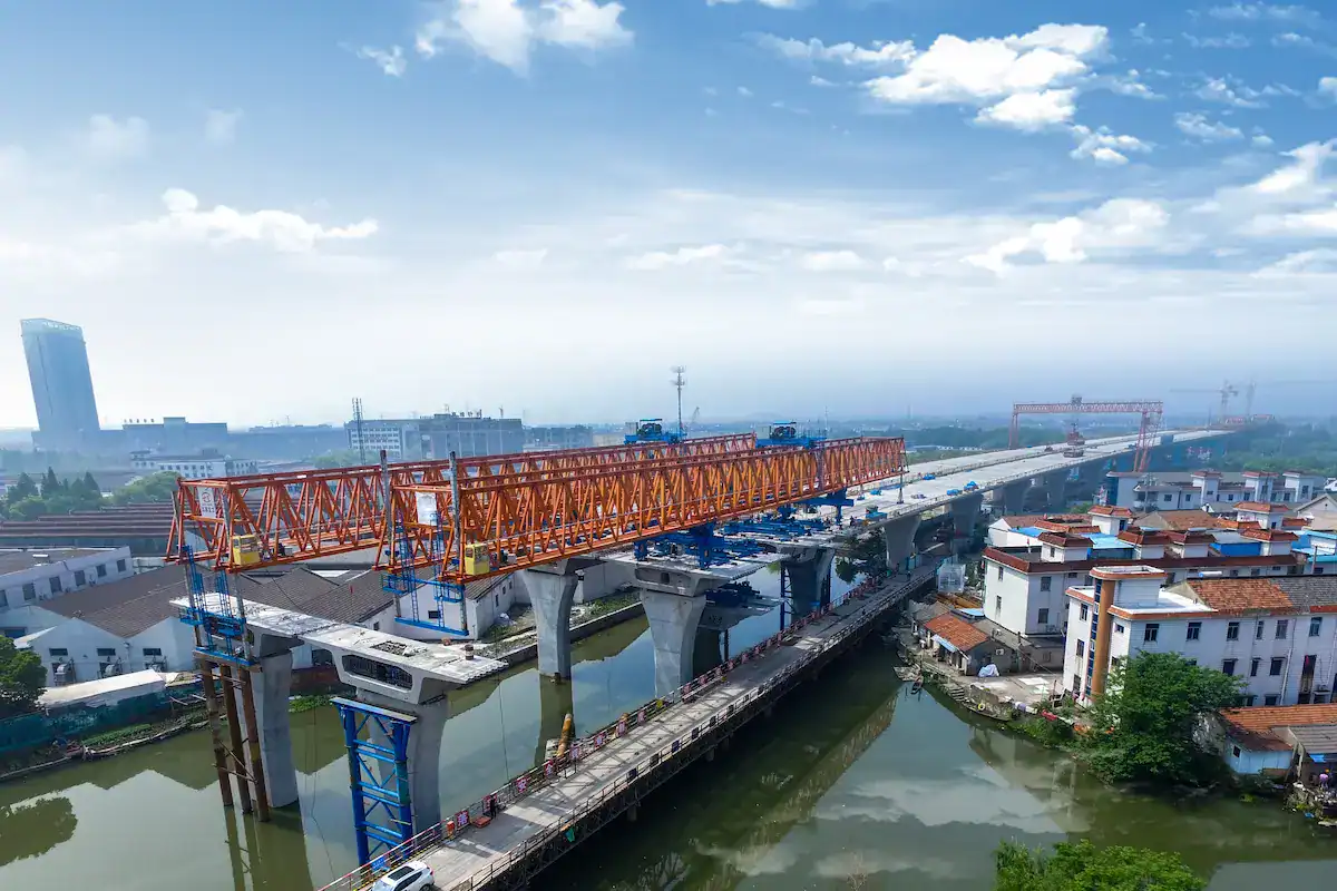
Key Technology Analysis of Bridge Launching Gantry
In the design of longitudinal and transverse systems, key technologies determine operational precision, safety, and intelligence. Advanced control and safety frameworks significantly enhance stability in complex construction environments.
Synchronous Control Technology
Due to the massive span of a bridge launching gantry, inconsistent motor speeds can cause structural twisting (known as “crabbing”). This may lead to jammed rails or fatigue damage.
- Multi-Motor Synchronous Drive:We use a Master-Slave control logic. The master motor follows a set curve. Slave motors track the master’s speed and position via real-time communication links within milliseconds. This ensures perfectly parallel travel.
- Variable Frequency Drive (VFD) Application:Beyond energy saving, VFDs provide smooth acceleration and deceleration. By setting an “S-curve” profile, the system offsets inertial impact during lifting and travel. This prevents massive horizontal thrust on the bridge piers.
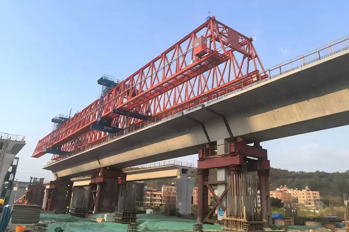
Safety Protection System
Safety is the baseline of gantry design. HSCRANE integrates a three-tier safety protection architecture:
Limit Protection:
- Level 1: Electronic limit switches trigger automatic deceleration at rail ends.
- Level 2: Final limit switches directly cut the control circuit power.
- Level 3: Mechanical buffers provide the ultimate physical barrier.
Overload Protection: Integrated load sensors monitor main beam stress in real-time. The system issues audio-visual warnings at 105% of rated load. At 110%, it automatically locks all hoisting and travel movements.
Emergency Braking System: Besides electromagnetic motor brakes, heavy-duty legs feature hydraulic rail clamps. During power failure or high winds, these clamps use spring force or hydraulic energy to bite the rail, preventing equipment drift.
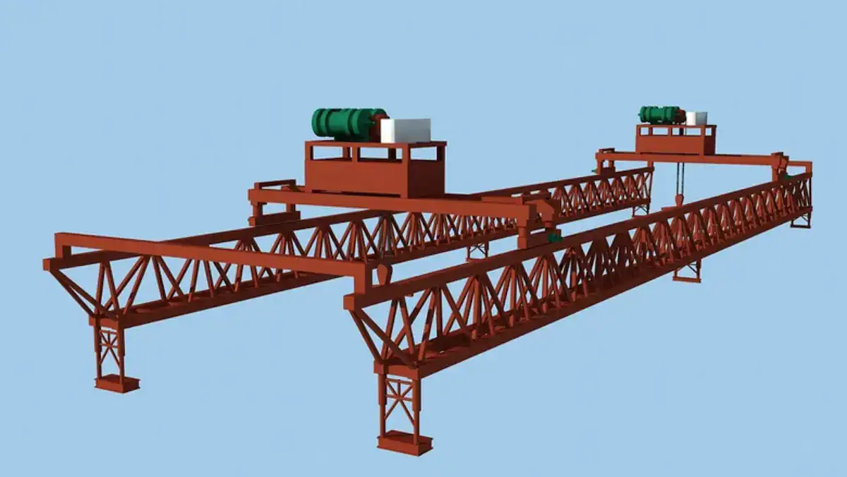
Intelligence and Automation Trends
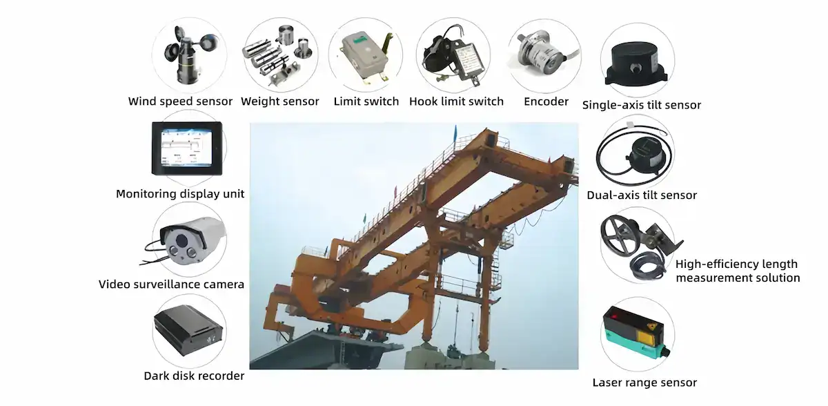
- PLC Control System:As the core unit, the PLC handles logic control and data processing. Modular programming and multi-signal management allow for automated and standardized operations, boosting overall efficiency.
- Remote Monitoring and Diagnostics:Using IoT technology, the gantry supports remote status monitoring. It collects real-time data from key components. If an anomaly occurs, the system locates the fault point instantly to reduce downtime.
- Smart Construction Applications:Gantries are evolving toward fully autonomous operation. Features like auto-positioning, path planning, and intelligent leveling allow for higher precision with minimal human intervention in complex conditions.
Top 3 Causes of Gantry Misalignment During Bridge Launching Gantry & How to Fix Them
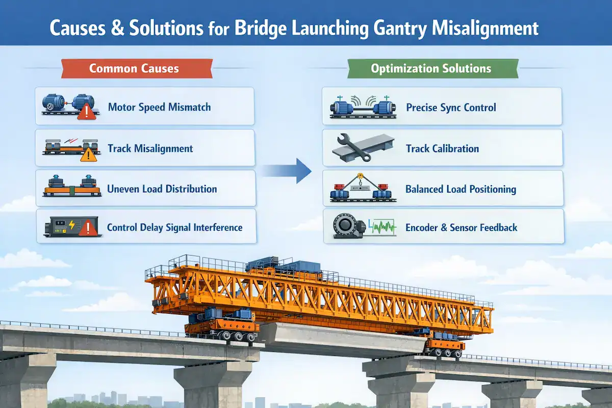
In actual bridge construction, the longitudinal and transverse systems of a bridge launching gantry are often affected by structural errors, environmental factors, and control precision. Analyzing typical problems and taking effective optimization measures is key to ensuring smooth construction.
Causes and Solutions for Non-Synchronized Travel
Common Causes:
- Speed differences or inconsistent parameter settings among multiple drive motors.
- Rail installation errors or local surface unevenness.
- Uneven load distribution leading to varying forces on drive units.
- Control system response delays or signal interference.
Optimization Solutions:
- High-Precision Sync: Use master-slave control logic or closed-loop control systems.
- Rail Calibration: Perform precise installation and regular calibration of rail alignment.
- Load Balancing: Optimize the beam lifting position to ensure even force distribution.
- Real-time Feedback: Introduce encoders and sensors to achieve millisecond-level corrections.
Measures for Excessive Transverse Deviation
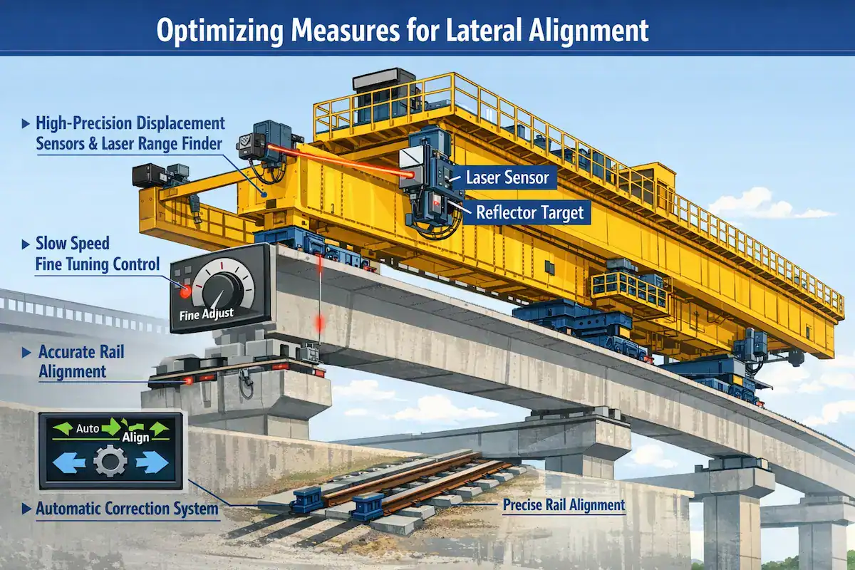
Problem Manifestation: Large positioning errors or difficulty in alignment during lateral movement, which impacts installation accuracy.
Optimization Solutions:
- Precision Sensing: Use high-precision displacement sensors and laser ranging systems to improve targeting.
- Micro-Inching Mode: Adopt a low-speed “inching” control mode for fine adjustments.
- Mechanical Refinement: Improve the installation precision of transverse rails to reduce mechanical backlash.
- Auto-Correction: Implement an automatic steering correction system to fix deviations in real time.
Solutions for Complex Conditions (Skewed & Curved Bridges)
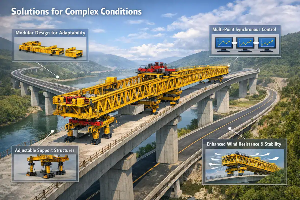
Challenge Analysis: On skewed bridges, curved bridges, or river crossings, the running trajectory is complex and forces shift constantly. This demands higher equipment stability and control logic.
Solutions:
- Modular Design: Enhances the equipment’s adaptability to various bridge profiles.
- Adjustable Support: Use adjustable support structures to match different bridge geometries.
- Dynamic Adjustment: Utilize multi-point synchronization and dynamic adjustment technology to ensure smooth travel.
- Wind Resistance: Strengthen structural design and stability analysis to improve safety in high-altitude or coastal environments.
Why Choose HSCRANE Bridge Launching Gantry?
HSCRANE is committed to providing superior lifting solutions for global road and bridge projects. Our systems offer significant competitive advantages:
Customized System Design
We do not offer “one-size-fits-all” solutions. Using Finite Element Analysis (FEA), we tailor drive power and rail structures based on specific loads, spans, and slopes.
High-Precision Sync Control
Equipped with advanced PLC closed-loop algorithms and VFDs, our synchronization error is kept within ±3mm. This prevents structural twisting and wheel-rail wear.
Reinforced Safety Design
All products strictly comply with CE, ISO, and FEM international standards. Systems integrate triple-limit protection, smart anti-tip alarms, and fail-safe hydraulic brakes.
Reliable Structural Integrity
Built with high-strength low-alloy steel, key stress points are annealed to eliminate internal stress. Self-adaptive equalizing wheel sets ensure smooth operation even on uneven rails.
Global Project Experience
With a track record of over 500 large-scale bridge projects (including high-speed rail and sea-crossing bridges), we provide full-lifecycle service from design to on-site guidance.
Summarize
The longitudinal and transverse movement systems are the “lifelines” of a bridge launching gantry. From the robust load-bearing of the travel mechanism to the VFD-synchronized control of multiple motors, every design detail determines the success of bridge installation.
Looking ahead, bridge launching gantry technology is accelerating toward intelligence, automation, and modularity. Through PLC integrated control and remote monitoring systems, construction sites will achieve a higher level of digital management. HSCRANE remains at the industry forefront. Our modular component designs allow equipment to quickly adapt to diverse conditions like high-speed rail, highways, and urban transit. This significantly shortens construction cycles and reduces labor costs.
Start Your Precision Construction Journey
No matter how complex your terrain or how strict your schedule, HSCRANE technical experts can provide the most efficient longitudinal and transverse solutions.
- Get Professional Technical Consultation:Our engineers will provide a preliminary plan within 24 hours.
- Request Product Manuals:Learn more about our high-precision synchronization technology compliant with CE/ISO standards.
- Contact Us:Click here to call our official service hotline.
You might also be interested in:
Even the best movement system is useless if it cannot withstand strong winds.
[Deep Feature] Anti-Wind and Anti-Tip Design: How HSCRANE Protects Beams and Equipment in Sudden Gales.
[Learn more about wind stability technology → High-Altitude Erection: Ensuring Launching Gantry Stability in Strong Winds]
FAQ
Q1: How does the gantry prevent "runaway" risks during longitudinal movement?
A1: The safety core lies in “multi-stage braking.” HSCRANE uses a dual locking mechanism: fail-safe electromagnetic brakes + hydraulic rail clamps. If the system loses power or sensors detect abnormal wind speeds, the rail clamps instantly bite the track. This ensures the equipment stays steady even on sloped sections.
Q2: Does HSCRANE's movement system support high-altitude or extreme cold environments?
A2: Yes. For extreme environments, we use low-temperature toughened steel and electrical cabinets with automatic heating units (IP66 protection). This ensures hydraulic oil does not solidify and electrical components do not frost, allowing stable operation from -25°C to +50°C.
This document is for reference only. Specific operations must strictly comply with local laws and regulations and equipment manuals.

Get Expert Advice for Your Bridge Project
Our engineering team brings decades of experience in bridge construction equipment. Let us help you find the right solution.
 Scan to chat